Gn94dnsrsa, Indoor tankless water heater, For answers to your monogram – GE GN94DNSRSA User Manual
Page 3: Ge profile, Or ge, Specification created 1/08
For answers to your Monogram,
®
GE Profile
™
or
GE
®
appliance questions, visit our website at
ge.com or call GE Answer Center
®
service,
800.626.2000.
380301
Specification Created 1/08
GN94DNSRSA
GE
®
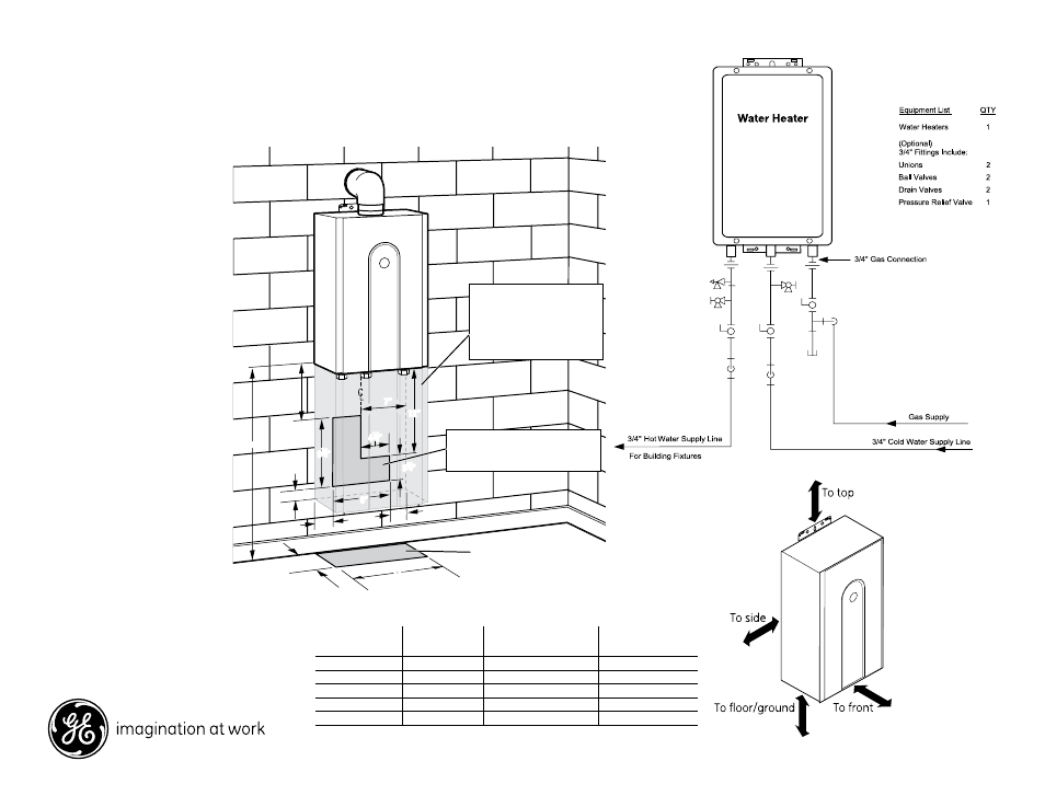
Indoor Tankless Water Heater
Dimensions and Installation Information (in inches)
Installation:
Planning for plumbing
(shown with optional pipe cover)
The center of the pipes can be
placed anywhere within the
shaded area.
The center of the pipes is
recommended to be protruding
only within 6" of the mounting
wall. Other specific installations
may be different.
Be sure that the minimum
elevation of the bottom of
the unit is 18" to meet the 36"
recommended clearance for the
exhaust.
Note: It is recommended to install
the bottom of the unit at least
18" off the ground to minimize
blockage from debris and provide
room for the optional Pipe Cover
Accessory, AGTPCM.
Clearances for tankless gas water heater (inch/mm)
To
combustibles
To
non combustibles
For servicing
and operation
Top of heater
12 (305)
2 (51)
2 (51)
Back of heater
0 (0)
0 (0)
0 (0)
Front of heater
24 (610)
24 (610)
24 (610)
Sides of heater
6 (152)
1/2 (13)
1/2 (13)
Floor/Ground
12 (305)
2 (51)
2 (51)
Pipe cover not required. However,
consideration should be taken in the
design of the rough plumbing to allow
installation of unit and pipe cover.
Optional Pipe Cover (AGTPCM)
shown shaded.
* Suggested area for Water and Gas lines to
come through the wall to allow the optional
pipe cover to be installed if desired.
Water and Gas
from below
9
7
⁄
8
”
2
1
⁄
2
”
2
1
⁄
2
”
2
1
⁄
2
”
4
1
⁄
2
”
7”
12”
3
3
⁄
8
”
6”
12”
9”
Floor
Unit
18” min.
18” min.
6
1
⁄
2
”
9
7
⁄
8
”
2
1
⁄
2
”
2
1
⁄
2
”
2
1
⁄
2
”
4
1
⁄
2
”
7”
12”
3
3
⁄
8
”
6”
12”
9”
Floor
Unit