FUJITSU CG-301 User Manual
Page 7
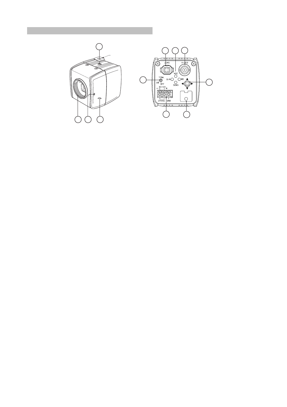
EXTERNAL CONTROLS AND CONNECTORS
TOP/FRONT VIEW
3
3
2
1
CAMERA MOUNT
ADAPTER
6
8
9
10
4
7
5
BACK VIEW
①
Lens Mount
The camera has a standard CS lens mount but can use a C-mount lens when a C/CS-mount adapter is installed
between the lens and camera.
②
Back Focus Lock Screw
Loosen to adjust the back focus to match the lens attached to the CS mount. Refer to the section on Back Focus
Adjustment in this manual.
③
Camera Mounts
Top or bottom mounting. Maximum thread length is 3/16-inch. Attach the camera mount adapter to extend
thread depth to a standard 1/4-inch.
④
Video Output Connector
This coaxial connector (BNC type) outputs the video signals.
⑤
Lens Connector
Four-pin DC-control connector for auto iris lens. Refer to the section on Lens in this manual for pin connections.
⑥
RS485 Terminating Switch
This is the switch to terminate between signals of RS-485.
ON : Terminated with 100 ohm. OFF : Not terminated
⑦
LEDs
LEDs light up or blink while using Direct-key function and displaying Camera Setup Menu.
Refer to the section on Setting Operation in this manual.
⑧
Setup Switch
This is the switch to display and operate the menu when OSD function is used. And when Direct-key function is
used, it is used for the selection of ON or OFF. Refer to the section on Setting Operation in this manual.
⑨
Power Input Terminal
Three-pin terminal strip, push-in type; 24 VAC/12 VDC for NTSC/PAL
models.
⑩
External Control Input Terminal
This is the I/O terminal of the signal with an electronic characteristic in accordance with RS-485 standard. In
addition, it is the control signal input terminal for DAY&NIGHT function.
En-6
Fig.1