Changing the routing tool, Changing the clamping collet – Festool MFK 700 User Manual
Page 10
10
b) Router table for edge veneer
The "router table for edge veneer" (only in SET
scope of delivery) is designed for fl ush trim-
ming veneer overhang and profi le routing.
Notes:
The router table is tilted 1.5° so that the
f
surface coating is not damaged during edge
routing. A router table with 0° inclination
angle for precise cuts is available as an
accessory.
5-1
5-2
1
2
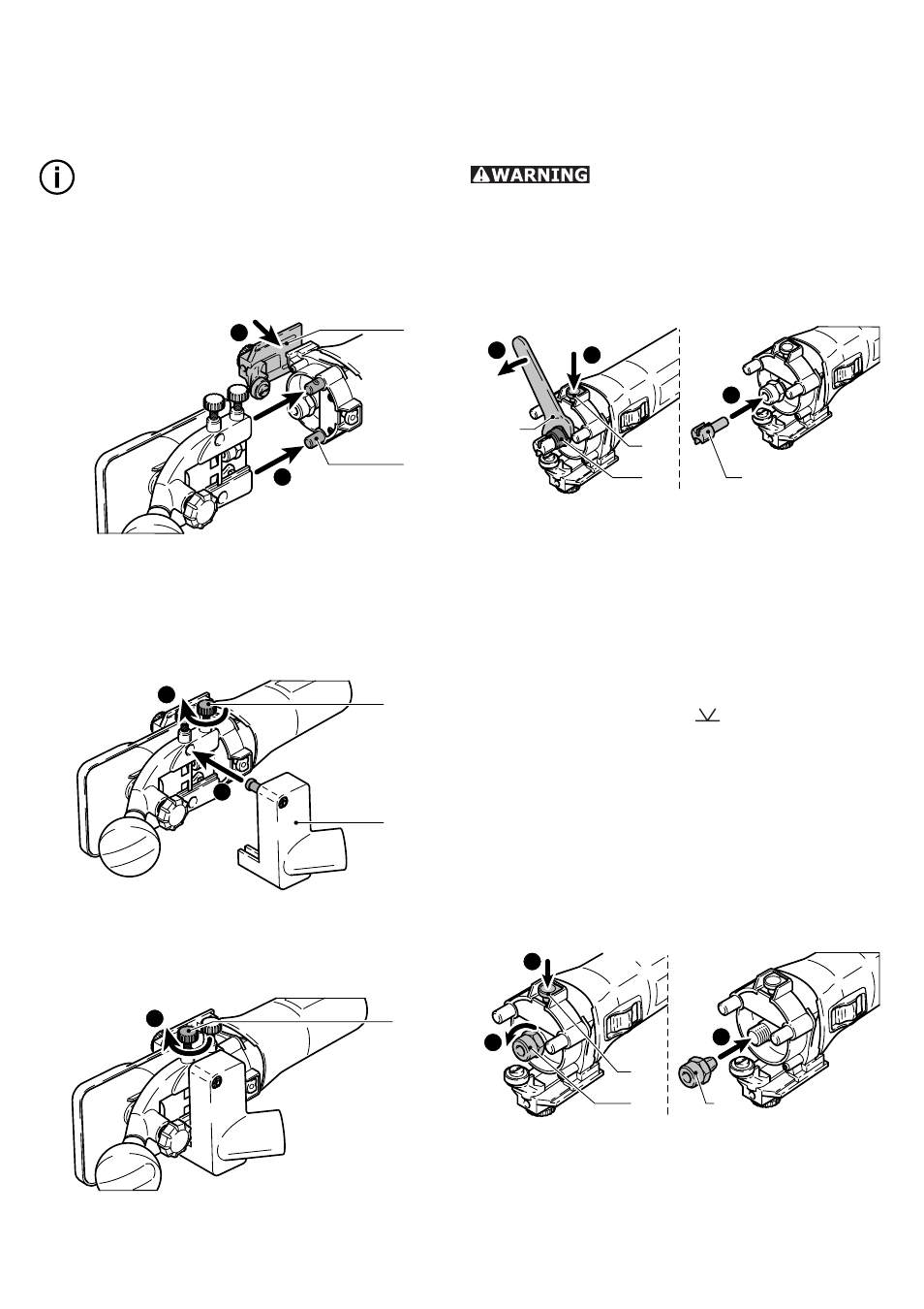
Secure the sensor [5-1] to the machine
–
using the preassembled screws. Slide the
sensor in the long holes to adjust the rout-
ing tool to the perfect position.
Slide the router table onto the retaining pin
–
[5-2] on the machine.
5-3
5-4
3
4
Tighten the screw [5-3] to clamp the router
–
table in position.
Place the extraction hood [5-4] in posi-
–
tion.
5-5
5
Tighten the screw [5-5] to clamp the ex-
–
traction hood in position.
Removal is performed in reverse sequence to
installation.
Changing the routing tool
Risk of accident - the routing
tool may be hot after use and has sharp
edges. Allow the tool to cool before chang-
ing. Wear protective gloves when changing
tools.
Remove the router table before changing
–
the routing tool.
SW 19
6-2
6-3
6-1
1
2
3
a) Removing the tool
Press the spindle lock [6-1].
–
Unscrew the locking nut [6-2] using the
–
open-end wrench (size 19) until you are
able to remove the tool.
b) Inserting the tool
Insert the routing tool [6-3] into the open
–
clamping collet as far as possible, but at
least up to the mark (
) on the shank.
Press the spindle lock [6-1].
–
Tighten the locking nut [6-2] using the
–
open-end wrench (size 19).
Changing the clamping collet
Only compatible tools can be used in com-
bination with the clamping collets supplied.
8 mm, 6 mm and 1/4" (6.35 mm) clamping
collets can be used.
7-2
7-3
7-1
1
2
3
Press the spindle lock [7-1].
–
Unscrew the locking nut [7-2] completely.
–
Remove the locking nut from the spindle
–
together with the clamping collet [7-3]. Do
not separate the locking nut and clamping
collet as these form a single component.