Installation, Continued – FMI VFP18MV User Manual
Page 12
12
105071
UNVENTED PROPANE/LP GAS LOG HEATER
FIREPLACE MANUFACTURERS INC.
Pressure Testing gas Supply
Piping system
Test Pressures In Excess Of 1/2 PSIG
(3.5 kPa)
1.
Disconnect appliance with its appliance
main gas valve (control valve) and
equipment shutoff valve from gas sup-
ply piping. Pressures in excess of 1/2
psig will damage heater regulator.
2.
Cap off open end of gas pipe where
equipment shutoff valve was con-
nected.
3.
Pressurize supply piping system by ei-
ther using compressed air or opening
propane/LP supply tank valve.
4.
Check all joints of gas supply piping
system. Apply mixture of liquid soap
and water to gas joints. Bubbles form-
ing show a leak.
5.
Correct all leaks at once.
6.
Reconnect heater and equipment
shutoff valve to gas supply. Check re-
connected fittings for leaks.
WARNING: Never use an open
flame to check for a leak. Apply a
mixture of liquid soap and water
to all joints. Bubbles forming
show a leak. Correct all leaks at
once.
WARNING: Test all gas pip-
ing and connections for leaks
after installing or servicing. Cor-
rect all leaks at once.
CAUTION: Make sure exter-
nal regulator has been installed
between propane/LP supply and
heater. See guidelines under
Con-
necting to Gas Supply, page 11.
CHECKING GAS
CONNECTIONS
Test Pressures Equal To or Less Than
1/2 PSIG (3.5 kPa)
1.
Close equipment shutoff valve (see Fig-
ure 15).
2.
Pressurize supply piping system by ei-
ther using compressed air or opening
propane/LP supply tank valve.
3.
Check all joints from propane/LP sup-
ply tank to equipment shutoff valve (see
Figure 16). Apply mixture of liquid
soap and water to gas joints. Bubbles
forming show a leak.
4.
Correct all leaks at once.
INSTALLATION
Continued
Pressure Testing Heater Gas
Connections
1.
Open equipment shutoff valve (see
Figure 15).
2.
Open propane/LP supply tank valve.
3.
Make sure control knob of heater is in
the OFF position.
4.
Check all joints from equipment shutoff
valve to control valve (see Figure 16). Ap-
ply mixture of liquid soap and water to
gas joints. Bubbles forming show a leak.
5.
Correct all leaks at once.
6.
Light heater (see Operating Heater,
pages 14 and 15). Check all other in-
ternal joints for leaks.
7.
Turn off heater (see To Turn Off Gas to
Appliance, page 15).
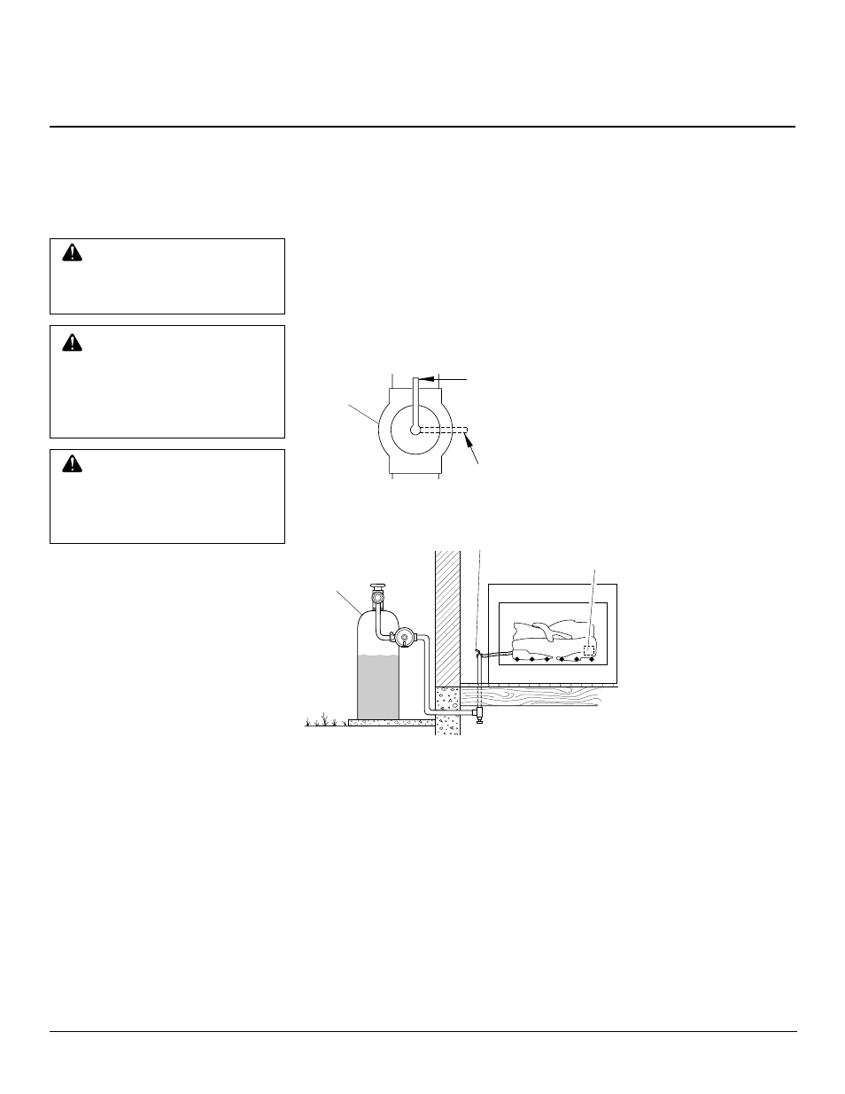
Figure 15 - Equipment Shutoff Valve
Figure 16 - Checking Gas Joints
Control Valve
Location
Propane/
LP Supply
Tank
Equipment
Shutoff Valve
ON
POSITION
OFF
POSITION
Open
Closed
Equipment
Shutoff
Valve