Installation instructions for pre-rinse units, Installation instructions continued, Iis sh he er r iis sh he er r iis sh he er r – Fisher 34436 User Manual
Page 2
IIS
SH
HE
ER
R
IIS
SH
HE
ER
R
IIS
SH
HE
ER
R
PS T
Installation Instructions for Pre-Rinse Units
BE SURE TO CHECK WITH YOUR LOCAL DEPARTMENT HAVING JURISDICTION
REGARDING BACKFLOW PREVENTION
Installation Notes:
• Be sure to shut off water supply before beginning.
• Use pipe thread sealant such as PST on all threaded joints.
• Check the packaging for missing items BEFORE beginning installation. If items are missing, contact your supplier.
Tools Required for Installation
• Medium Sized Crescent Wrenches
• Pipe Thread Sealant
• Phillips Screwdriver
• 7/16” Drill Bit
• 1/8” Allen Wrench
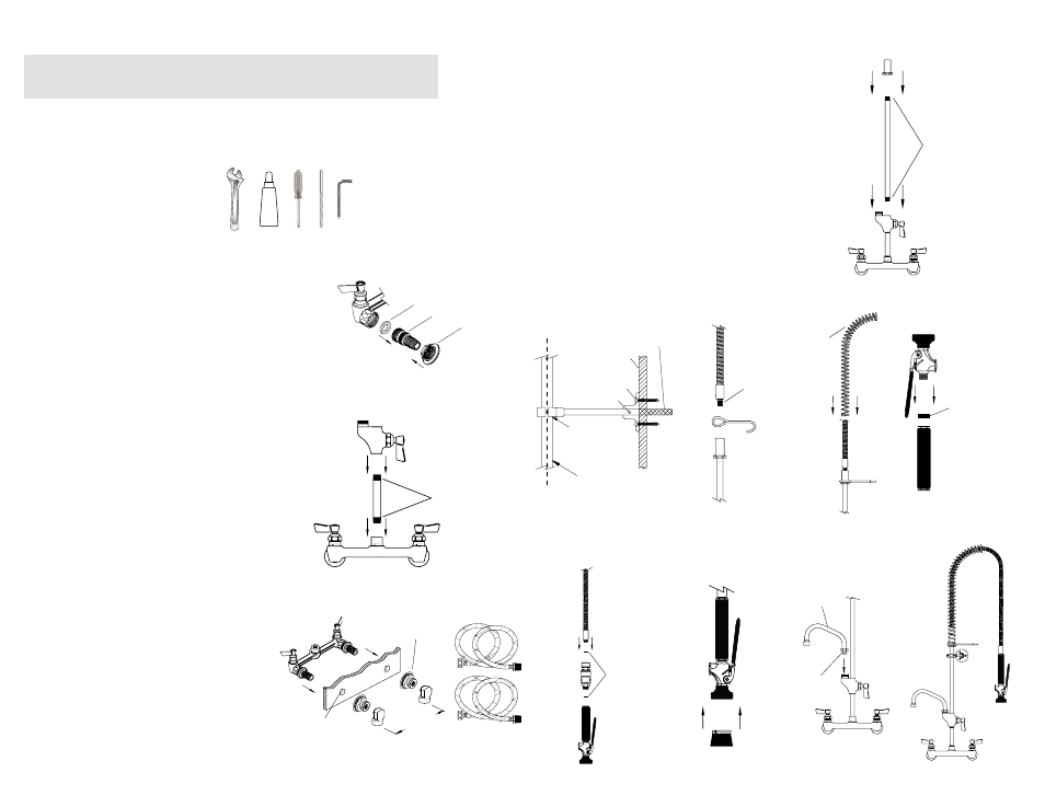
Installation Instructions
1. Insert the gasket into the groove on the concentric.
Making sure the gasket is in place, loosely mount
the concentrics and fl ange onto the control valve
body.
2. Mount the small riser to the control valve body
using thread sealant. Screw the add-on faucet to
the other end of the small riser, again using thread
sealant.
3. Mount control valve body to the backsplash by in-
serting the concentrics through the backsplash and
attaching slip joints. Attach elbows or supply lines
and tighten concentrics. Be sure to use pipe thread
sealant on all threads.
4. Mount the pipe to hose adapter to the enclosed
riser using thread sealant. Mount the other end of
the riser to the female outlet of the add-on body.
5. If no wall bracket is to be installed, proceed to Step
6, otherwise do the following:
a. Locate and drill a Ø7/16” hole in the wall directly
behind and about 3/4 the way up the riser pipe.
b. Loosely attach the front and back of the pipe
clamp onto the riser pipe.
c. Hold the wall bracket fl ange against the wall,
centered with the hole. Use the wall screws and
a screw driver to mount the fl ange to the wall.
d. Slide part, but not all, of the wall bracket rod non-
threaded end fi rst through the center hole of the
fl ange and into the wall.
e. Align the rod with the pipe clamp and thread the
rod into the pipe clamp. Be sure the rod is level
by adjusting the pipe clamp position.
f. Once level, fi x the rod in place by tightening both
the set screw located in the fl ange and the pipe
clamp screws.
6. Slip the hose hook over the pipe to hose adapter.
Using thread sealant and a crescent wrench, thread
the SS hose into the pipe to hose adapter.
7. Install gooseneck spring by slipping SS hose
through the spring. Spring will fi t over adapter which
holds it in an upright position. Note: Be sure spring
is installed as shown. DO NOT INSTALL SHORT
BEND DOWN.
Step 1
Step 2
Step 3
Gasket
Concentric
Flange
7
3
/
4
” - 8
1
/
4
”
[196.9 - 209.6mm]
Thread Sealant
Goes Here
Slip Joints
Ø7/8”
PREVENTER
BACK-FLOW
WATTS N9
IIS
SH
HE
ER
R
IIS
SH
HE
ER
R
IIS
SH
HE
ER
R
IIS
SH
HE
ER
R
IIS
SH
HE
ER
R
IIS
SH
HE
ER
R
IIS
SH
HE
ER
R
IIS
SH
HE
ER
R
IIS
SH
HE
ER
R
8. Fit one of the handle gaskets inside the outlet of the
insulated handle and mount the spray valve onto it.
9. Fit the other handle gasket inside the inlet of the
insulated handle and mount the handle onto the
SS hose. If installing backfl ow preventer, attach it
between the SS hose and insulated handle. Be sure
that gaskets are used on both sides of the backfl ow
preventer
10. If installing a brush, do so by pressing brush into
the bumper of the spray valve until secure.
11. To install swing spout to add-on faucet, apply
o-ring lube to the o-rings on the swing spout.
Make sure the white snap ring is in place before
mounting the swing spout. Mount the swing spout
and tighten the swing spout nut onto the add-on
faucet spout outlet.
12. Turn on water supply and check for leaks.
Installation Instructions Continued
Step 7
Step 8
Step 9
Step 10
Step 11
Step 5
Step 6
Step 4
Thread Sealant
Goes Here
Spring Bend
On This Side
Handle Gasket
Apply O-Ring
Lube Here
Swing Spout
Handle Gasket
Excess Rod Length
Trim to Fit (optional)
Pipe
Clamp
Riser Pipe
Set Screw
Wall Screw
Wall
Thread Sealant
Goes Here
Step 12