Finisar Single Mode XENPAK Transponder FTLX1461E2 User Manual
Page 2
FTLX1461E2 Product Specification – October 2008
© Finisar Corporation – October 2008
Rev B
Page 2
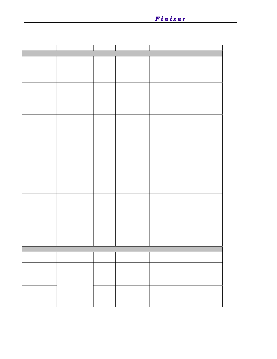
I. PIN DESCRIPTION
Signal Name
Level
I/O
Pin No.
Description
Management and Monitoring Ports
MDIO
Open Drain
I/O
17
Management Data I/O. Requires
external 10 - 22 kΩ pull-up to the
APS on host.
MDC 1.2
V
CMOS
I
18
Management Data Clock Input
PRTAD4 1.2
V
CMOS
1
19
Port Address Input bit 4
PRTAD3 1.2
V
CMOS
I
20
Port Address Input bit 3
PRTAD2 1.2
V
CMOS
I
21
Port Address Input bit 2
PRTAD1 1.2
V
CMOS
I
22
Port Address Input bit 1
PRTAD0 1.2
V
CMOS
I
23
Port Address Input bit 0
LASI
Open Drain
O
9
Link Alarm Status Interrupt Output.
Open Drain Compatible Output with
10 - 20 kΩ pull-up on host.
Logic high = Normal Operation
Logic low = Status Flag Triggered
RESET Open
Drain
I 10
Reset
Input.
Open Drain Compatible Input with
22 kΩ pull-up to APS internal to
transponder.
Logic high = Normal Operation
Logic low = RESET
Vendor Specific
11,15,16,24
Vendor Specific Pins.
Leave unconnected when not used.
TX ON/OFF
Open Drain
I
12
TX ON/OFF Input.
Open Drain Compatible Input with
22 kΩ pull-up to APS internal to
transponder.
Logic high = Transmitter On
Logic low = Transmitter Off
MOD DETECT
O
14
Pulled low inside transponder
through a 1 kΩ resistor to Ground
Transmit Functions
Reserved
Reserved
I
I
68
67
Reserved For Future Use
Reserved For Future Use
TX LANE 3–
TX LANE 3+
I
I
65
64
Module XAUI Input Lane 3–
Module XAUI Input Lane 3+
TX LANE 2–
TX LANE 2+
I
I
62
61
Module XAUI Input Lane 2–
Module XAUI Input Lane 2+
TX LANE 1–
TX LANE 1+
I
I
59
58
Module XAUI Input Lane 1–
Module XAUI Input Lane 1+
TX LANE 0–
TX LANE 0+
AC-coupled,
Internally biased
differential
XAUI
I
I
56
55
Module XAUI Input Lane 0–
Module XAUI Input Lane 0+