Manual line feed m, Cutting head, Np q – Flymo POWER TRIM 600 HD User Manual
Page 6: Q1 p1
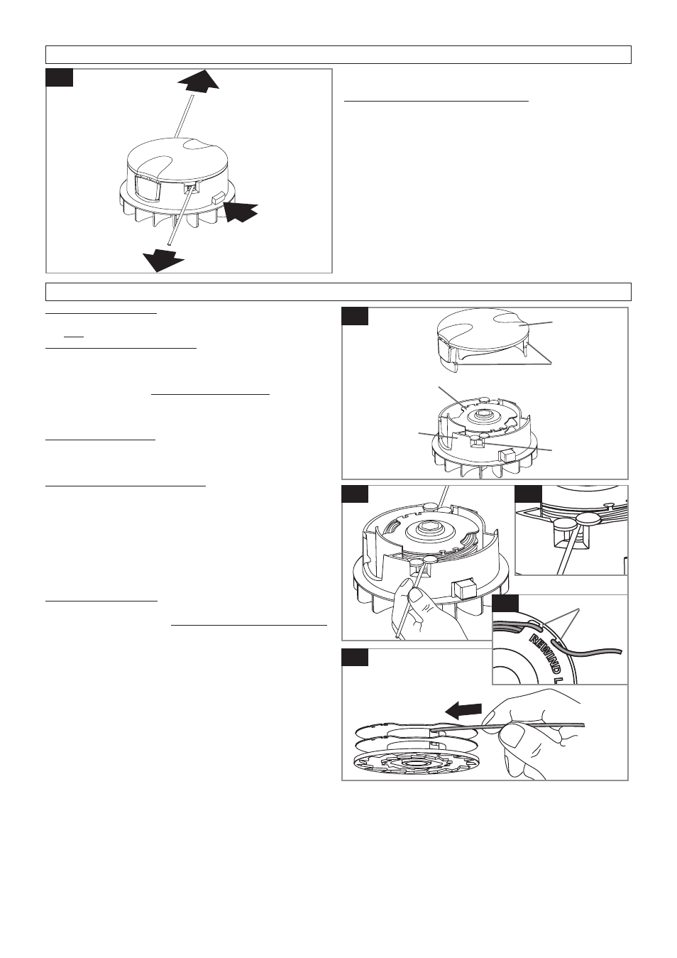
To manually feed the nylon line (M)
1. If required line can be fed out manually.
2. To operate, press and release manual line feed but-
ton, whilst gently pulling on one of the lines until the
line reaches the line cutter.
3. When the required amount of line is fed out, gently
pull on the second line (there is no need to press the
manual line feed button again).
4. If the line extends past the line cutter, too much line
has been fed out.
5. If too much line is fed out, remove the spool cap and
click spool anti-clockwise until the line is at the desired
length.
Manual line feed
M
manual line
feed button
Cutting Head
To remove spool cap
1. Press and hold in the two cap release latches. (N).
2. Pull cap away from the spoolholder. (N).
When refitting the spool cap
1. Keep all areas of the cap and spoolholder clean.
Failure to do so may prevent the cap being securely
located in the spoolholder.
2. Replace the cap, pressing firmly DOWN towards
the spoolholder to ensure cap is fully located.
3. Check that the cap is correctly fitted by trying to re-
move it without depressing the two latches.
To replace nylon line
For your convenience it is recommended you buy spool
and line complete. Nylon line only is also available. Both
are available from Husqvarna UK Ltd. stockists.
To fit spool and line complete:
1. Remove the cap.
2. Remove old spool.
3. Place spool into spoolholder.
4. Release one line from cleat (Q1).
5. Secure line into slot (P1).
6. Repeat for second line.
•
Ensure spool is fully located by gently rotating it during
fitment, whilst keeping the spoolholder steady.
7. Refit the cap.
To fit nylon line only:
•
Remember !
Your Flymo Trimmer is designed to use
only nylon line with a maximum diameter of 2.0mm.
Use only genuine Flymo nylon line.
1. IMPORTANT - Always wind the line onto the upper
section of the spool first.
Take approximately 5 metres of line. Insert 15mm of
line into one of the holes in the upper section of the
spool (Q) and wind line in the direction of the arrows
on the top of the spool. Leave approximately 100mm
of line unwound and place into cleat as illustrated in
figure Q1. Repeat on lower section of spool.
2. Care should be taken to ensure that the line is neatly
coiled on the spool. Failure to do so will impair the ef-
ficiency of the automatic line feed.
3. Then fit spool as described in ‘To fit spool and line
complete’
, section above.
Cap
Cap release
latch
Spool
Spoolholder
Slot
N
P
Q
Cleat
Q1
P1