Field Controls SWGII-6 User Manual
Page 3
page 3
INSTALLATION
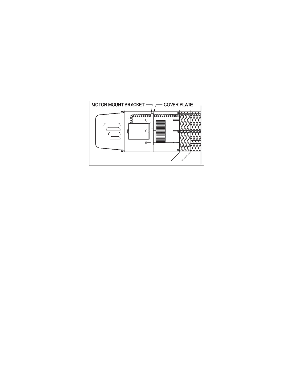
1. Align the holes in the circular cover plate with the holes in the motor mount bracket on the motor
assembly. (See Figure 3)
2. Slide the motor assembly onto the protruding threaded studs on the power venter body with the exhaust
chute pointing downward, and replace the nuts securely to the threaded studs. (See Figure 3)
3. Use the top knockout on the electrical box and reattach the fl exible conduit and wires to the motor using
the conduit connector and wire nuts. Secure the cover on the electrical box.
4. Seal around the edge of the motor mount bracket with the provided high temperature silicone sealant.
Install the motor cover with the side louvers pointing downward. (See Figure 1)
Figure 3
MAINTENANCE
1. Motor: Inspect the motor once a year - motor should rotate freely. To prolong the life of the motor, it must be
lubricated with six drops of SWG Superlube, Part # 46226200, annually. NOTE: Some models may have sealed-
bearing motors, which do not require lubrication.
2. Wheel: Inspect the power venter wheel annually to clear any soot, ash or coating which inhibits either rotation
or air fl ow. Remove all foreign materials before operating.
3. Vent System: Inspect all vent connections annually for looseness, for evidence of corrosion and for fl ue gas
leakage. Replace, seal or tighten pipe connections if necessary. Check the power venter choke plate to ensure
it is secured in place. Check the barometric draft control, if installed, to ensure the gate
swings freely.
4. System Safety Devices: With the heating system operating, disconnect the pressure sensing tube from
the pressure switch on the CK Kit. This will stop the burner operation. Re-connecting the tube will relight
the burner. For 30 millivolt operating systems, disconnect one lead of the spill switch circuit from the
thermocouple junction block. This will shut off the pilot and the burner. Re-connection will allow relighting
the pilot.