Furuno NX-700B User Manual
Page 48
4. INSTALLATION
4-2
Flush mounting
The display unit can be installed flush mounted in a console or panel by using
the optional flush mount kit.
(For NX-700A)
Type: OP08-19
Code No.: 004-515-260
Name Type
Code
No.
Qty Remarks
Mounting metal
08-023-1019
100-326-960
1
Self-tapping screw
5X20
000-802-081
6
Hex. bolt
M8x15
000-862-144
2
Spring washer
M8
000-864-262
2
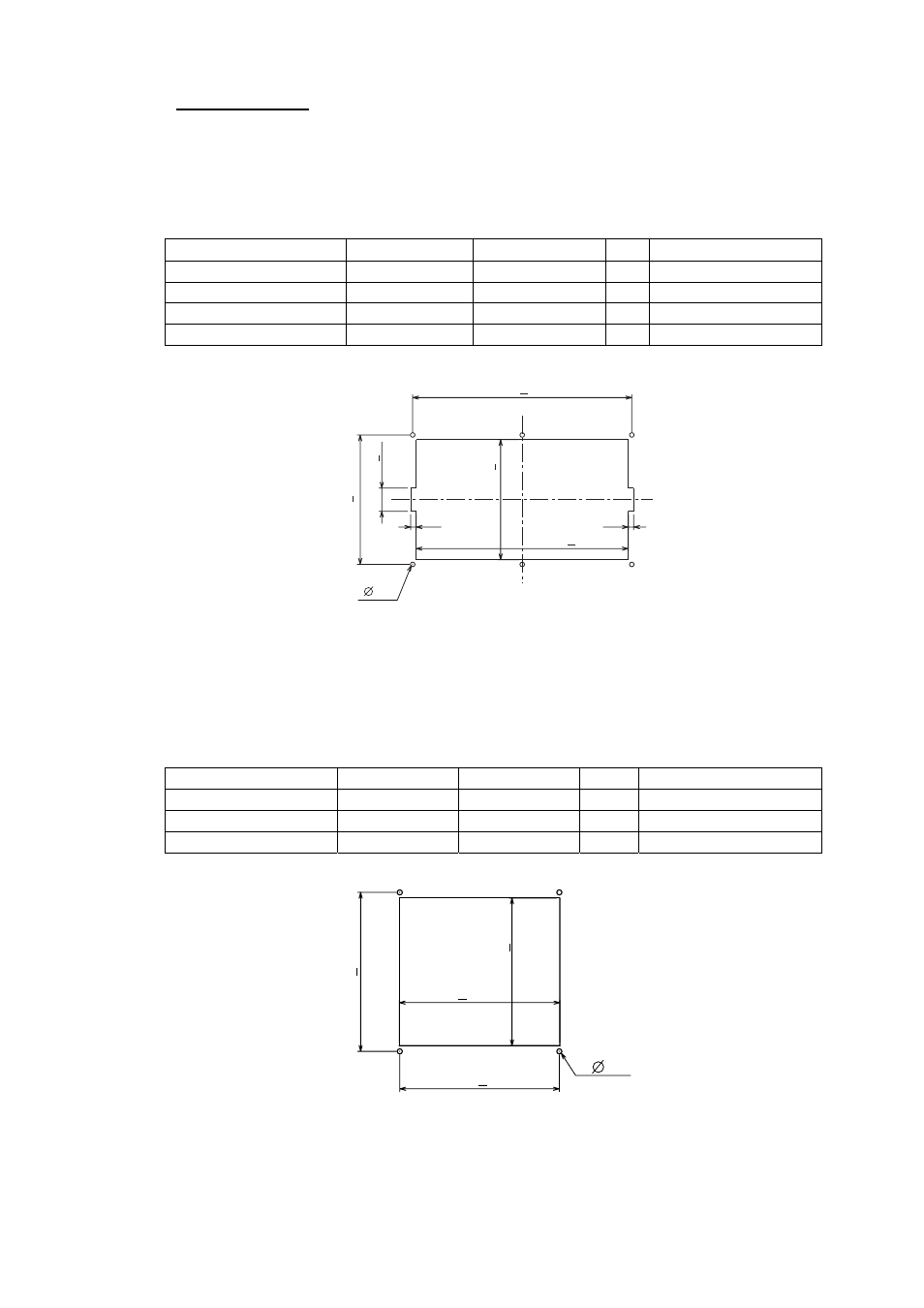
1. Cut out a hole with dimensions as shown below in the mounting location.
7
275+1
156+1
284+0.5
30+1
168+0.5
7
4
Fixing hole
2. Attach the fixing metal to the display unit with two hex. bolts (M8x15,
supplied with optional kit) and spring washers (supplied with optional kit).
3. Fasten six self-tapping screws to fix the display unit to the mounting location.
(For NX-700B)
Type: OP08-20
Code No.: 004-515-270
Name Type
Code
No.
Qty
Remarks
Mounting metal
08-023-2011
100-327-010 1
Self-tapping screw
5x20
000-802-081 4
Pan head screw
M4x12
000-802-130 4
1. Cut out a hole with dimensions as shown below in the mounting location.
156+1
155+0.5
144+1
155+0.5
4
Fixing hole
2. Attach the fixing metal to the display unit with four pan head screws (M4X12,
supplied with the optional kit).
3. Fasten four self-tapping screws (supplied with the optional kit) to fix the
display unit to the mounting location.