Heart rate target zone for cardiovascular fitness, Assembly instructions – Fitness Quest 475u User Manual
Page 7
19
6
TABLE 2
Exercise
Warm Up
THR%
Cool Down
Total
Sessions
Total Time
Week
Period
Minutes
Period
Time
Per Wk.
Per Wk.
&
1 & 2
5 min
60-65% -8
5 min
17 min
3
51 min
&
3 & 4
5 min
65-70% -10
5 min
20 min
3
60 min
&
5 & 6
5 min
70-75% -15
5 min
25 min
3
75 min
&
7 & 8
5 min
70-80% -20
5 min
30 min
3
90 min
&
9 & 10
5 min
70-85% -25
5 min
35 min
3
105 min
&
11 & 12
5 min
70-85% -25
5 min
35 min
3
105 min
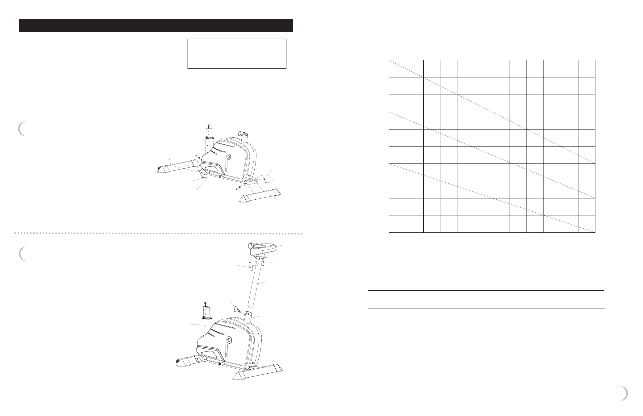
HEART RATE TARGET ZONE
FOR CARDIOVASCULAR FITNESS
TABLE 1
Maximum
Attainable
Heart Rate
85%
Target
Zone
70%
Target
Zone
Heart
Rate
(Beats/
Min)
20
25
30
35
40
45
50
55
60
65
70
75
80
200
190
180
170
160
150
140
130
120
110
100
195
165
136
190
161
133
185
157
129
180
153
129
175
148
129
170
144
119
165
140
115
160
136
112
155
131
108
150
127
105
145
123
101
140
119
98
AGE (YRS)
STEP 1 – Attaching the Foot Tubes
to the Main Frame
a) Attach the Front Foot Tube to the front of
the Main Frame using two Allen Bolts with
a Flat Washer on each Bolt.
a) Attach the Rear Foot Tube to the rear of
the Main Frame using two Allen Bolts
with a Flat Washer on each Bolt.
front foot tube
main frame
M8 flat washer
main
frame
seat
support
tube
M8 nylon nut
seat
M8 washer
adjustment
knob
rear tube
M8 flat
washer
M8 x 20mm allen bolt
M8 x 20mm
allen bolt
rear
foot tube
STEP 2 – Installing the Seat Assembly to
the Main Frame
a) Remove the Nylon Nuts and Washers from the Seat.
b) Place the Seat on the Seat Support Tube.
c) Place the Washers and the Nylon Nuts on the
bottom of the Seat and securely tighten the Nuts.
d) Insert the bottom of the Seat Support Tube
into the Rear Tube of the Main Frame; the
Adjustment Knob must be pulled in order
to insert the Seat Support Tube.
Occasionally our products contain components that are
pre-lubricated at the factory. We recommend that you
protect flooring, or anything else the parts may contact,
with newspaper or cloth.
ASSEMBLY INSTRUCTIONS
Figure 1 - Install Foot Tubes to Main Frame
Figure 2 - Install Seat to Main Frame
FRONT
REAR
NOTE: All location references, such as
front, rear, left or right, made in these
instructions are from the user being
on the equipment and facing forward.
Tools Required (included):
Allen Wrench
Multi Open End Wrench
Multi “T” Tool w/Phillips Screwdriver