Floscan Instrument TWINSCAN 3TB013U User Manual
Page 16
5/20/1999
1000-207-00
FloScan Instrument Company, Inc.
Tel: (206) 524-6625 Fax: (206) 523-4961
3016 NE Blakeley Street, Seattle, WA 98105 email: [email protected] http://www.floscan.com
III.
ALTERNATOR
The alternator input usually comes off one of the windings of the alternator before it is rectified. This tachometer signal is
inconsistently inaccurate because of a varying amount of belt slippage depending on the load on the alternator, the dimension of the
belt and the belt tension.
Calibration
You can calibrate the tachometer by two methods:
1. Calibrate to the existing tachometer. Simply rotate the RED and BLACK knobs on the back of the instrument until the two
tachometers agree with each other. The accuracy of this method depends on the accuracy of the existing tachometer at the
RPM to which you calibrate. It is best to compare to the existing tachometer at cruising RPM or higher, not at idle.
2. You need the number of poles the alternator has to determine the number of pulses per revolution. Multiply this times the
ratio of the diameter of the crankshaft pulley. Divide this number by the diameter of the alternator pulley.
3. Locate the number of pulses per crankshaft revolution in Table 1. Select the number closest to your actual pulses per
crankshaft revolution.
Example: Motorola alternator has 12 pole pairs (12 pulses per revolution)
Crank shaft pulley = 10” diameter Alternator pulley = 4” diameter
12 x (10
÷ 4) = number of pulses per revolution 12 x 2.5 = 30 pulses per revolution.
From Table 1 - 50 RPM synchronized resolution - RED switch = 8
BLACK switch = 3
20 RPM synchronized resolution - RED switch = 8
BLACK switch = B
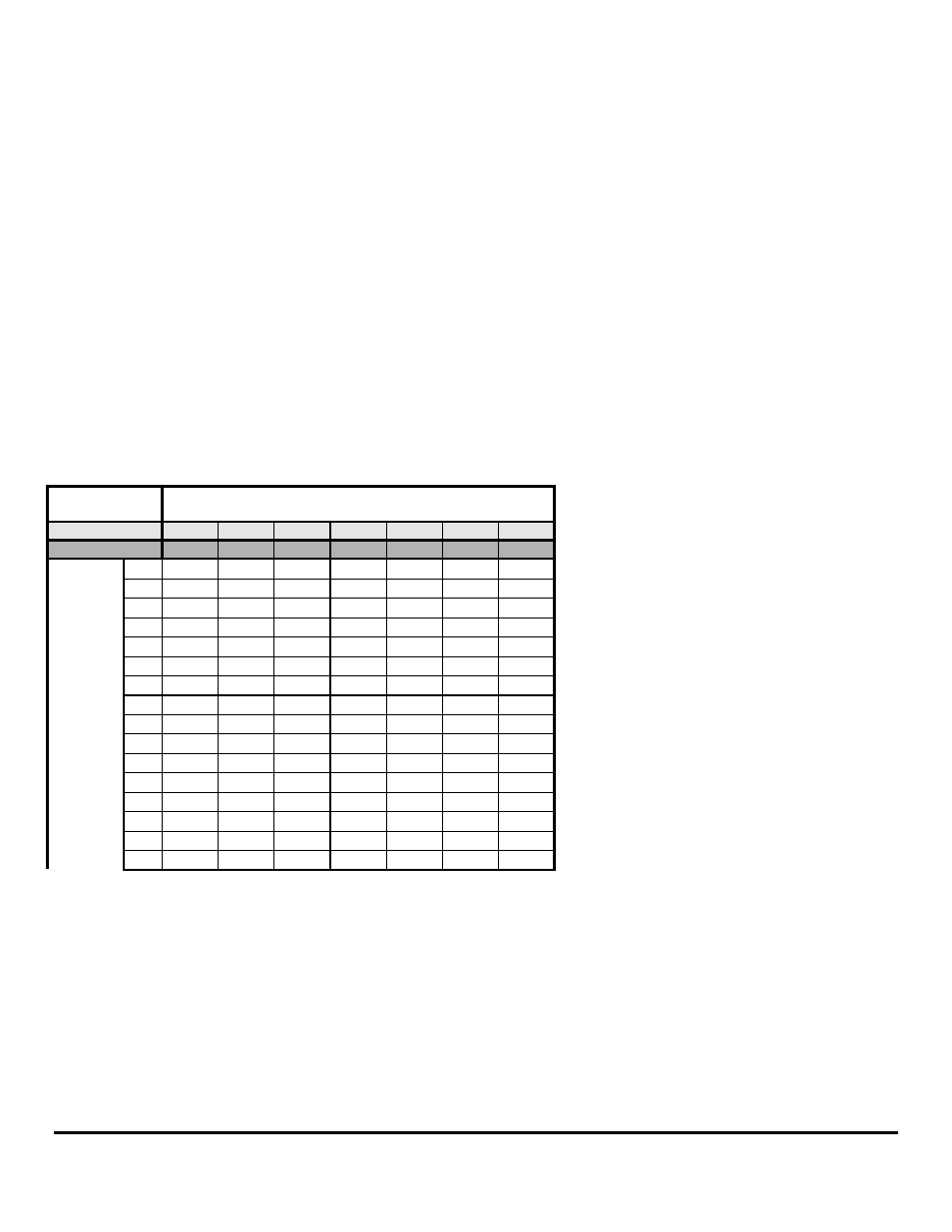
Adjust the RED and BLACK switches for the pulses per revolution according to Table 1:
Synchronized
Resolution
BLACK Switch Setting
20 RPM
9
A
B
C
D
E
F
50 RPM
1
2
3
4
5
6
7
0
1.00
13.9
23.8
39.5
63.5
111
190
1
2.00
14.3
24.5
41.0
66.0
114
196
2
3.00
14.6
25.3
42.5
69.0
117
202
3
4.00
15.0
26.0
44.0
72.0
120
208
4
5.00
15.4
26.8
45.5
75.0
123
214
5
6.00
15.8
27.5
47.0
78.0
126
220
RED
6
7.00
16.3
28.3
48.5
81.0
130
226
Switch
7
8.00
17.0
29.0
50.0
84.0
136
232
Setting
8
9.00
17.8
29.8
51.5
87.0
142
238
9
10.0
18.5
30.5
53.0
90.0
148
244
A
11.0
19.3
31.3
54.5
93.0
154
250
B
12.0
20.0
32.0
56.0
96.0
160
256
C
12.4
20.8
33.5
57.5
99.0
166
268
D
12.8
21.5
35.0
59.0
102
172
280
E
13.1
22.3
36.5
60.5
105
178
292
F
13.5
23.0
38.0
62.0
108
184
304
Table 1 Tachometer Calibration