Caution, Wiring – Honeywell C7046A User Manual
Page 2
C7046A,B,C,D AIR TEMPERATURE SENSORS
62-0216
2
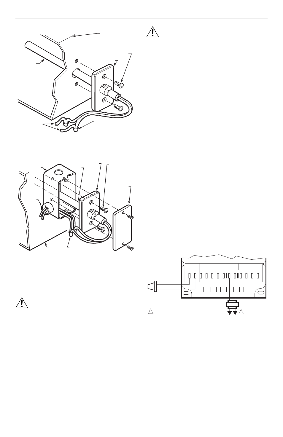
Fig. 2. Mounting C7046 Air Temperature
Sensor on a flat duct or plenum surface.
Fig. 3. Mounting C7046 Air Temperature
Sensor in a junction box.
Wiring
CAUTION
Electrical Shock or Equipment Damage
Hazard.
Can shock individuals or short equipment
circuitry.
Disconnect power supply before installation.
CAUTION
Erratic System Operation Hazard.
Failure to follow proper wiring practices can
introduce disruptive electrical interference
(noise).
Keep wiring at least one foot away from large
inductive loads such as motors line starters,
lighting ballasts, and large power distribution
panels.
Shielded cable is required in installations where
these guidelines cannot be met.
Ground shield only to grounded controller case.
IMPORTANT
1. All wiring must agree with applicable codes,
ordinances and regulations.
2. Do not mount sensor in incorrect environment.
3. Wire according to the applicable controller
instructions.
4. Erratic temperature readings from a sensor can
be caused by improper wiring practices. These
must be avoided to assure proper operation:
•Avoid poor wiring connections.
•Avoid intermittent or missing building earth
ground.
•Do not mount sensor in incorrect environment.
Connect low voltage wiring from the sensor to the
appropriate system component terminals using
solderless connectors. See Fig. 3.
NOTES:
1.
For connections to the W973 Single Zone
Logic Panel, see Fig. 4.
2.
For connections to the W7080 Multizone
System, see Fig. 5.
3.
For connections to the Excel 500 Control
System, see Fig. 6.
4.
For additional wiring information, refer to the
appropriate specification.
Fig. 4. Connecting C7046A Air Temperature
Sensor to a W973 Single Zone Logic Panel.
SENSOR
PROBE
SYSTEM DUCT
OR PLENUM
FLANGE
NO. 8 (4mm)
MOUNTING SCREWS
(NOT PROVIDED)
TO
APPROPRIATE
SYSTEM
COMPONENTS
CONNECT SENSOR
WIRES WITH TWO
WIRENUT CONNECTORS
(NOT PROVIDED)
M22403A
SENSOR
PROBE
SYSTEM
DUCT OR
PLENUM
FLANGE
STANDARD UTILITY
CONDUIT BOX
CONNECTOR
LOCKNUT
AND
CONDUIT
BLANK
FACEPLATE
(OPTIONAL)
TO APPROPRIATE
SYSTEM
COMPONENTS
CONNECT SENSOR WIRES
WITH TWO WIRENUT
CONNECTORS (NOT PROVIDED)
M22404A
NO. 8 (4 mm)
MOUNTING
SCREWS (NOT
PROVIDED)
R
T
T1 3
4
2
5
1 T RT R W B Y
R
SENSOR
STAT
24 VAC
ECONO
C +20 H N
1
C7046A
L1
(HOT)
L2
W973 LOGIC PANEL
M17965
1
POWER SUPPLY. PROVIDE DISCONNECT
MEANS AND OVERLOAD PROTECTION
AS REQUIRED.