GE Profile 30 Inch Combination Wall Oven Installation Instructions User Manual
Warning
2 C
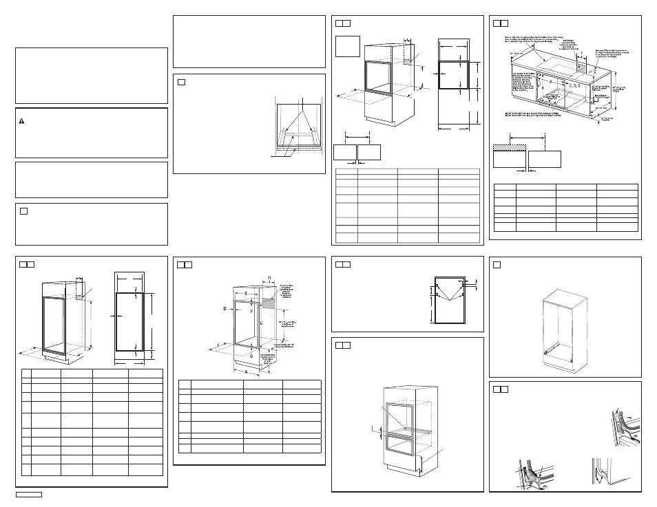
CUTOUT FOR DOUBLE OVENS (2 THERMAL OVENS)
NOTE: If the cabinet does not have a front frame and the sides are less than ¾” (1.9 cm) thick, shim
both sides equally to establish the cutout width.
Dim.
Description
27” Double Oven
30” Double Oven with
Pedestal
30” Double Oven
without Pedestal
A
Cabinet Width
27” (68.6 cm)
30” (76.2 cm)
30” (76.2 cm)
B
Cutout Width
25” (63.5 cm) min.
25
1
ø
4
” (64.1 cm) max.
28
1
ø
2
” (72.4 cm) min.
28
5
ø
8
” (72.7 cm) max.
28
1
ø
2
” (72.4 cm) min.
28
5
ø
8
” (72.7 cm) max.
C
Cutout Height
49
11
ø
16
” (126.2 cm) min.
50
1
ø
8
” (127.3 cm) max.
51
13
ø
16
” (131.6 cm) min.
51
15
ø
16
” (131.9 cm) max.
50 ¼” (127.64cm)
D
Overlap of Oven
Over Side Edges
of Cutout
1” (2.5 cm)
11
ø
16
” (1.75 cm)
11
ø
16
” (1.75 cm)
E
Clearance to
Adjacent Corners,
Drawers, Walls, etc.,
When Door Is Open
23” (58.4 cm) min.
23” (58.4 cm) min.
23” (58.4 cm) min.
F
Overlap of Oven
Top of Cutout
1” (2.5 cm) min.
1” (2.5 cm) min.
(1
1
ø
4
” (3.2 cm) for PT9550)
1” (2.5 cm) min.
(1
1
ø
4
” (3.2 cm) for PT9550)
G
Overlap of Oven
Bottom of Cutout
1” (2.5 cm) min.
1
1
ø
4
” (3.2 cm)
1
1
ø
4
” (3.2 cm)
H
Junction Box
Location
8
3
ø
4
” (22.2 cm) max.
right side only
9
1
ø
2
” (24.1 cm) max.
right side only
9
1
ø
2
” (24.1 cm) max.
right side only
J
Height to Bottom
of Junction Box
44” (111.8 cm)
47” (119.4 cm)
47” (119.4 cm)
K
Recommended
Cutout Location
from Floor
13
1
ø
4
” (33.7 cm)
12” (30.5 cm)
12” (30.5 cm)
2 A
CUTOUT FOR SINGLE OVENS IN WALL CABINET
NOTE: If the cabinet does not have a front frame and the sides are less than ¾” (1.9 cm) thick, shim
both sides equally to establish the cutout width.
BEFORE YOU BEGIN
Read these instructions completely and
carefully.
•
,03257$17³
Save these instructions
for local inspector’s use.
•
,03257$17³
Observe all governing
codes and ordinances.
• Note to Installer – Be sure to leave these
instructions with Consumer.
• Note to Consumer – Keep these instructions
for future reference.
• Skill level – Installation of this appliance
requires a qualified installer or electrician.
• Proper installation is the responsibility
of the installer.
• Product failure due to improper installation
is not covered under Warranty.
• Product is for indoor use only.
Installation Instructions
27” & 30” Electric Built-In Wall Ovens
FOR YOUR SAFETY:
WARNING:
Before beginning the installation, switch power off at the service panel and
lock the service disconnecting means to prevent power from being switched on accidentally. When the
service disconnecting means cannot be locked, securely fasten a prominent warning device, such as a tag,
to the service panel.
Be sure the oven is securely installed in a cabinet that is firmly attached to the house structure.
Weight on the oven door could cause the oven to tip and result in injury. Never allow anyone to climb, sit,
stand or hang on the oven door.
Make sure the wall coverings, counters and cabinets around the oven can withstand the heat
(up to 200°F [93.3°C]) generated by the oven.
Questions?
Call 1.800.GE.CARES (1.800.432.2737) or visit www.GEAppliances.com
In Canada, call 1.800.561.3344 or visit www.GEAppliances.ca
MATERIALS YOU MAY NEED
Junction Box
Wire Nuts
Strain Relief Clamp for 1/2” Conduit
36” (91 cm) of String
TOOLS YOU MAY NEED
1/8” Drill Bit and Electric or Hand Drill
Phillips Screwdriver
Wire Strippers
7/16” Nut Driver
T20 Screwdriver (hinge bracket)
1/4” Nut Driver
1
REMOVE PACKAGING MATERIALS
Failure to remove packaging materials could result in damage to the appliance. Remove all packing
parts from oven, racks and heating elements. Remove protective film and labels on the outer door
and control panel. Also, remove plastic on trims and panel, all tape around the oven and any shipping
screws securing the oven to the base pad. Open oven door and remove literature pack and oven
racks. Remove the bottom trim from the top of the oven. It will be installed at the end of the installation
process. The trim is wrapped separately and taped to the top of the unit. Remove pedestal rails from
seperate box and set aside (30” Double Wall Ovens Only).
2
PREPARE THE OPENING
NOTE: If the cabinet does not have a solid bottom, two
braces or runners must be installed to support the weight
of the oven. For single ovens, the runners and braces
must support 200 lbs (91 kg). For double ovens, the
runners and braces must support 375 lbs. (170 kg).
NOTE: If marks, blemishes or the cutout opening are
visible above the installed oven, it may be necessary to
add wood shims under the runners and front trim until
the marks or opening are covered.
NOTE: If the cabinet does not have a front frame and
the sides are less than ¾” (1.9 cm) thick, shim both sides
equally to establish the cutout width.
ATTENTION INSTALLER:
All electric wall ovens must be hard-wired (direct-wired) into an
approved junction box. A plug and receptacle is NOT permitted on these products.
These ovens
are not
approved for
stackable
installations.
Cutout –
observe all
dimensions and
requirements.
Cutout –
observe all
dimensions and
requirements.
2” (5.1 cm) Min.
30.5” (77.5 cm)
30” models
27” (68.58 cm)
27” models
Center Line
Center Line
Side-by-Side Installations
Install two ovens in separate cutouts.
Dimension Dimension Description
27” Single Oven
30” Single Oven
A
Cabinet
Width
27” (68.6 cm)
30” (76.2 cm)
B
Cutout
Width
25” (63.5 cm) min.
28
1
ø
2
” (72.4 cm) min.
25
1
ø
4
” (64.1 cm) max.
28
5
ø
8
” (72.7 cm) max.
C
Cutout
Height 27
5
ø
8
” (70.2 cm) min.
27
1
ø
4
” (69.2 cm) min.
28
1
ø
8
” (71.4 cm) max.
27
5
ø
16
” (69.4 cm) max.
D
Overlap of Oven Over
1” (2.5 cm)
11
ø
16
” (1.75 cm)
Side Edges of Cutout
E
Clearance
to
23” (58.4 cm) min.
23” (58.4 cm) min.
Adjacent Corners,
Drawers,
Walls,
etc.,
When Door Is Open
F
Overlap of Oven
1” (2.5 cm) min.
1” (2.5 cm) min.
Top of Cutout
(1
1
ø
4
” (3.2 cm) for PT9050)
G
Overlap of Oven
1” (2.5 cm) min.
1
1
ø
4
” (3.2 cm)
Bottom of Cutout
H
Junction Box Location
8
3
ø
4
” (22.2 cm) max.
9
1
ø
2
” (24.1 cm) max.
right side only
right side only
Suitable
Bracing
to Support
CL
2" x 4" (5 cm x 10 cm)
or Equivalent Runners Level
with Bottom of Cutout
and Flush with Sides of Cutout
2 B
CUTOUT FOR SINGLE OVENS – UNDER COUNTER
NOTE: These ovens are only approved to be installed under the specific models as labeled on the unit.
Dimension Dimension Description
27” Single Oven
30” Single Oven
A
Cabinet
Width
25” (63.5 cm) min.
28
1
ø
2
” (72.4 cm) min.
25
1
ø
4
” (64.1 cm) max.
28
5
ø
8
” (72.7 cm) max.
B
Cutout
Height 27
5
ø
8
” (70.2 cm) min.
27
1
ø
4
” (69.2 cm) min.
28
1
ø
8
” (71.4 cm) max.
27
5
ø
16
” (69.4 cm) max.
C
Unit Overlap Top
1” (2.5 cm)
1” (2.5 cm)
(1
1
ø
4
” (3.2 cm) for PT9050)
D
Unit Overlap Bottom
1” (2.5 cm)
1
1
ø
4
” (3.2 cm)
E
Unit Overlap Side Edges 1”
(2.5
cm)
11
ø
16
” (1.75 cm)
F
Junction Box Location
8
3
ø
4
” (22.2 cm) max.
9
1
ø
2
” (24.1 cm) max.
right side only
right side only
Continue to Section 4.
NOTE: One cooktop may be centered over either oven in
the side-by-side installation.
Cutout – observe
all dimensions and
requirements.
2” (5.1 cm) Min.
30.5” (77.5 cm) 30” models
27” (68.58 cm) 27” models
Center Line
Center Line
Side-by-Side Installations
Install two ovens in separate cutouts.
Cooktop
Cutout – observe
all dimensions and
requirements.
2 F
CUTOUT FOR INSTALLATION OVER A WARMING DRAWER
NOTE: Install the oven only with specific models listed on the label located on top of the oven.
NOTE: Additional clearances between cutouts may be required. Check to be sure the oven supports
above the Warming Drawer location do not obstruct the required interior depth and height.
When installing a Warming Drawer below a single or double oven, a separate 120V, 60 HZ, properly
grounded receptacle must be installed. Refer to installation instructions packed with
the Warming Drawer for specific installation requirements.
2 E
SECURING UPPER MICROWAVE/ADVANTIUM OVEN TO CABINET
For double oven with microwave or Advantium upper ovens. Secure a wooden cleat to side of cabinet
so that the upper oven can be secured to the cleat with provided screws
27” Cabinet requirements
• No shims (or cleats) required when cabinet is in minimum
width condition.
• If cabinet is at maximum width condition, add wood
shims to bring cabinet to minimum condition.
30” Cabinet requirements
• No shims (or cleats) required when cabinet is in minimum
width condition.
• If cabinet is at maximum width condition, fix the wood
cleats as shown in illustration.
2 D
CUTOUT FOR DOUBLE OVENS (with Upper Microwave Oven)
NOTE: If the cabinet does not have a front frame and the sides are less than ¾” (1.9 cm) thick, shim
both sides equally to establish the cutout width.
Anti-Tip Block Against
Rear Wall Per Warming
Drawer Requirement
2" (5.1 cm)
Min.
Per Warming
Drawer
Requirement
Continue to Section 3 for DWO with Pedestal. Otherwise, continue to Section 4.
DESIGN INFORMATION
SINGLE OVEN INSTALLATIONS
The single oven may be installed in a cabinet alone or above a warming drawer. The single oven may also
be installed below a countertop or below specified cooktops. See the label on top of the oven for approved
models.
DOUBLE OVEN INSTALLATIONS
A double oven may be installed in a cabinet alone or above a warming drawer. See the label on top of the
oven for approved models.
IMPORTANT: Always refer to individual installation instructions packed with each product for specific
requirements.
Continue to Section 4
Continue to Section 4.
H
B
F
G
C
D
A
E
Junction
Box
Location
(junction
box may
be located
in adjacent
cabinet)
22” (55.9
cm) Min. to
Bottom of
Junction
Box
Cutout Depth
23-1/2”
(59.7 cm) Min.
Recommended
Cutout Location
from Floor
32-1/2” (82.6 cm)
Opening
Between Inside
Walls Must be
at Least 28-1/2”
(72.4 cm) Wide
H
B
C
K
F
G
D
A
J
E
Junction
Box
Location
(junction
box may
be located
in adjacent
cabinet)
Cutout Depth
23-1/2”
(59.7 cm) Min.
Note: Allow
1/4” (0.64 cm)
clearances
from side
edges of oven
door.
3
PEDESTAL RAIL INSTALLATION (30” DOUBLE OVENS ONLY)
A. Place one pedestal rail on each cabinet runner or centered on opposite side of solid cabinet bottom
flush with side of cabinet opening. Locate each rail so that front of rail is behind front cabinet
opening.
B. Drill pilot holes and attach rails to runner or bottom of cabinet with provided hardware.
Dim.
Description
27” Oven
with Microwave
30” Oven
with Microwave
A
Cabinet Width
27” (68.6 cm)
30” (76.2 cm)
B
Cutout Width
25” (63.5 cm) min.
25
1
ø
4
” (64.1 cm) max.
28
1
ø
2
” (72.4 cm) min.
28
5
ø
8
” (72.7 cm) max.
C
Cutout Height
41
1
ø
8
” (104.5 cm) min.
41
1
ø
4
” (104.8 cm) max.
42
3
ø
16
” (107.2 cm) min.
42
1
ø
4
” (107.3 cm) max.
D
Overlap of Oven Over Side Edges
of Cutout
1” (2.5 cm)
11
ø
16
” (1.75 cm)
E
Clearance to Adjacent Corners,
Drawers, Walls, etc., When Door
Is Open
23” (58.4 cm) min.
23” (58.4 cm)
F
Overlap of Oven Top of Cutout
1” (2.5 cm) min.
1” (2.5 cm) min.
G
Overlap of Oven Bottom of Cutout
1” (2.5 cm) min.
1
1
ø
4
” (3.2 cm)
H
Junction Box Location
8
3
ø
4
” (22.2 cm) max.
right side only
9
1
ø
2
” (24.1 cm) max.
right side only
6.375”
27.5”
1.5”
3.0”
Cleat locations on 30” cabinet
with maximum cutout condition
Wood Cleats
4 A
DOOR REMOVAL (RECOMMENDED)
NOTE: Door removal is not a requirement for installation of the product but is an added convenience.
To remove the door:
A. Open the oven door as far as it will go.
B. Remove hinge bracket from front frame and set aside. The hinge bracket must
be replaced for proper door functionality when door is reinstalled.
C. Push both hinge locks down toward the door frame to the unlocked position.
This may require a flat-blade screwdriver. DO NOT LIFT THE DOOR BY THE
HANDLE!
D. Place hands on both sides of the door and close the oven door to the removal
position (approximately 1”–2” [2.5 cm–5.1 cm] from the closed position).
E. Lift the door up and out until the hinge arms clear the slots.
NOTE: The oven door is very heavy. Be sure
you have a firm grip before lifting the oven door off the hinges. Use caution
once the door is removed. Do not lay the door on its handle.
This could cause dents or scratches.
Hinge Slot
Hinge Arm
Hinge Unlocked Position
Hinge Clears Slot
Hinge Bracket
31-10965-1
03-14 GE