Bestobell Steam FTH-10 Series Float & Thermostatic Trap User Manual
Pre-installation, Installation and operation, Initial warm-up
3170 Wasson Road • Cincinnati, OH 45209 USA
Phone 513-533-5600 • Fax 513-871-0105
[email protected] • www.bestobellsteamtraps.com
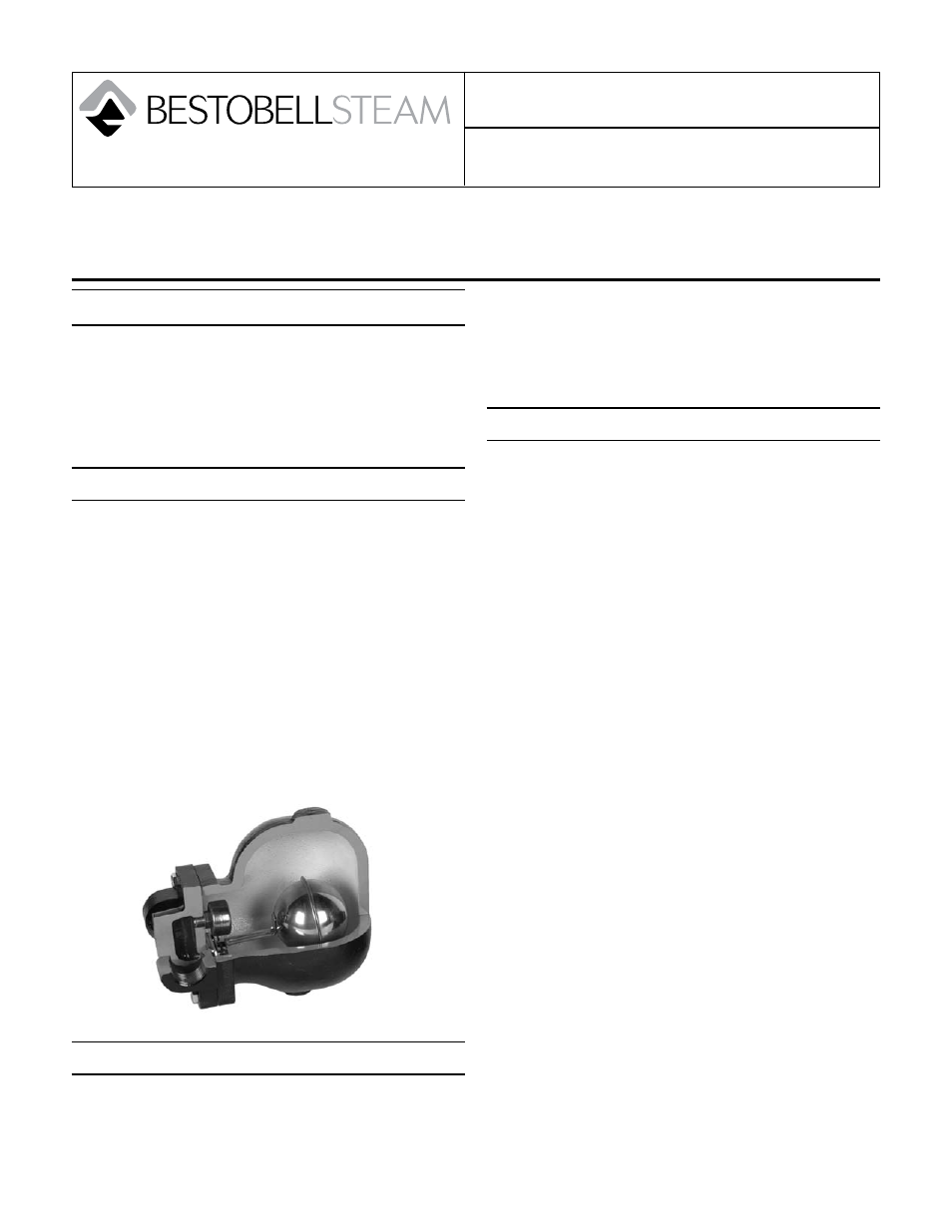
FTH-10 Series
Installation & Maintenance Instructions for
Bestobell Steam FTH-10 Series
Warning: Bestobell Steam products must only be used, installed and repaired in accordance with these Installation
& Maintenance Instructions. Observe all applicable public and company codes and regulations. In the event of leak-
age or other malfunction, call a qualified service person; continued operation may cause system failure or a general
hazard. Prior to servicing equipment, disconnect, shut off, drain and/or bypass all pressurized fluids.
Pre-Installation
Prior to installation:
Blow out piping to remove any scale or dirt.
•
Verify that your Bestobell steam trap will meet
•
system conditions by checking the nameplate for op-
erating differential pressure and maximum pressure
and temperature limits of the trap body.
Installation and Operation
The ball float is connected by a lever to the valve and
seat and, once the condensate reaches a certain level
in the trap, the float begins to rise. This opens the orifice
and the condensate drains until the float is lowered
and the valve seat rests tightly on the seat. The float is
positioned above the orifice so the condensate forms a
water seal and eliminates the loss of any live steam.
At the top of the trap is a thermostatic air vent that dis-
charges all air and non-condensable gases as soon as
they reach the trap. This allows for maximum condensate
drainage. The air vent reacts to the system temperature
and will close at a temperature a few degrees below
saturation point.
Initial Warm-up
As with all steam equipment, it is recommended that the
external gasketed joints be retorqued after a warm up/
cool-down cycle. Torque the cover bolts in a diagonal
sequence. Recommended cover bolt torque valves are:
1/2”
25 ft-lbs
3/4”
25 ft-lbs
1”
25 ft-lbs
1-1/2”
60 ft-lbs
2”
125 ft-lbs
Maintenance
NOTE: Trap users sometimes confuse flash steam with
leaking steam. If the steam blows out continuously, in
a blue stream, it is leaking steam. If steam floats out
intermittently, each time the trap discharges, in a whitish
cloud, it is flash steam. If traps are found to be leaking
steam, the following steps should be taken in the order
shown.
Warning: Be sure that there is no pressure in the trap
before loosening any fittings or joints. Shut off the
steam supply and allow the trap to cool to prevent
rupture or distortion of the float. Isolate connection
to condensate system as required.
Check that steam supply is shut off.
1.
Trap does not need to be removed from piping to do
2.
maintenance. Some hot condensate may be left in
trap, so allow trap to cool or remove Cover Bolts
slowly from around the flange. Lift off the body (2)
of steam trap, which will expose all internal working
components.
Wipe or rinse out interior of steam trap cover.
3.
Dismantle the valve mechanism by removing the Lever
4.
Pin (5) and pulling away the Float/Arm Plug (6). Float
can be removed from Lever, if required. Inspect seat
(4) and Plug (6) for any scale build-up, worn or pitted
seating surfaces. If slight evidence of above conditions
exist, then the seating surfaces can be touched up by
lapping the Plug to Seat by hand with a very fine grind-
ing compound paste. If the surfaces are badly pitted or
worn or do not clean up by above method, replace the
Seat and Plug.
To remove the Seat (4) on 3/4” and 1” traps, use a 5/8”
5.
socket over the Seat. On the 1-1/2” or 2” size, a 1-5/8”
socket is required. If the Seat has been removed, in-
spect its seating surface and clean the old gasket mate-
rial completely away. Replace Gasket (8) as required.