Rs232c serial-interface connections, Ps/2 mouse-port connections – Interlink Electronics DuraPoint User Manual
Page 11
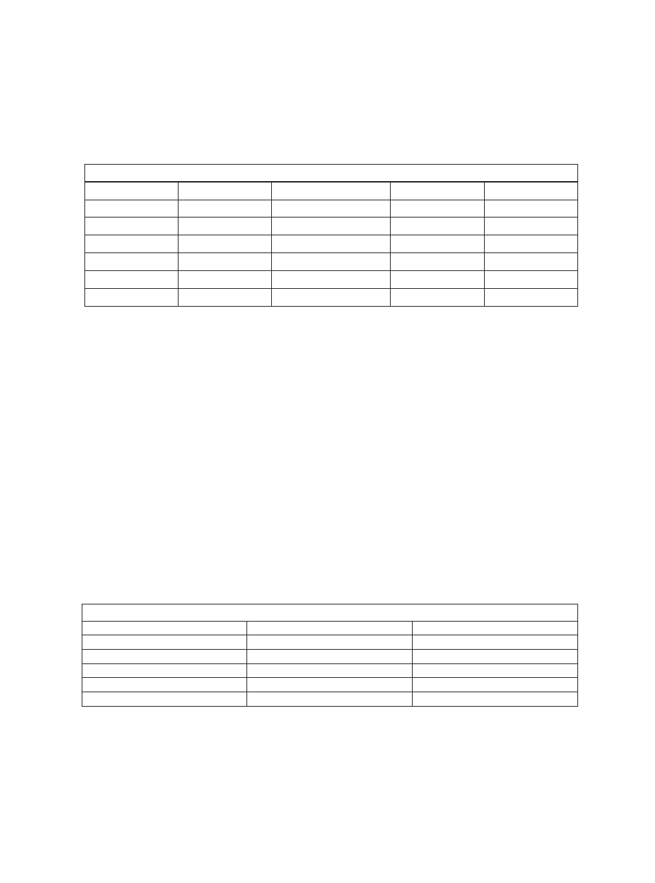
RS232C Serial-Interface Connections
* See Figure 7.13 for details on the PS/2 pin-out convention
** See Figure 7.08 for details on connecting the cable shield
The following table shows the pin-out for RS232C serial-data connections to the
J1 interface header. The J1 header is the 10-pin, double-row 0.1” center header on
the back of the DOM's circuit board. Also shown are the connections for standard
9-pin and 25-pin DB-style serial connectors. Five lines are needed for an RS232C
serial interface. See Figure 7.08 for details on the J1 pin-out convention.
* See Figure 7.13 for details on the DB-9 pin-out convention
** See Figure 7.08 for details on connecting the cable shield
PS/2 Mouse-Port Connections
®
The following table shows the pin-out of the J1 header that corresponds to a PS/2
mouse-port connection. Also shown are the connections for a standard 6-pin mini-
DIN PS/2 mouse-port connector. Four lines are needed for a PS/2 interface. See
Figure 7.08 for details on the J1 pinout convention.
The DOM uses standard Microsoft-compatible serial-data format (detailed infor-
mation on this data format is given in drawing VPDP-DOM120). In order for the
DOM to properly communicate to a system, a Microsoft-compatible mouse driver,
such as the Windows native mouse driver, will need to be installed (see the
DuraPoint User's Guide). Once the DOM is connected and the system restarted,
the DOM should operate properly.
Serial Pin-Out Information
J1 Header Pin
Signal
Signal Description
DB-9 Pin*
DB-25 Pin
1
GND
Ground
5
7
2
DTR
Data terminal ready
4
20
3
TXD
Transmit data
3
2
4
RXD
Receive data
2
3
9
RTS
Request to send
7
4
N/A
N/A
Cable Shield**
Shell
Shell
PS/2 Pin-Out Information
J1 Pin
Signal Description
mini-DIN 6 (PS/2) Pin*
1
Ground
3
5
Clock
5
7
Data
1
8
+5V
4
N/A
Cable Shield**
Shell
DuraPoint Integration Guide
Page 7