4 pcb keep out area – Interlink Electronics VersaPad USB User Manual
Page 13
USB VersaPad®
Integration Guide
www.interlinkelectronics.com
11
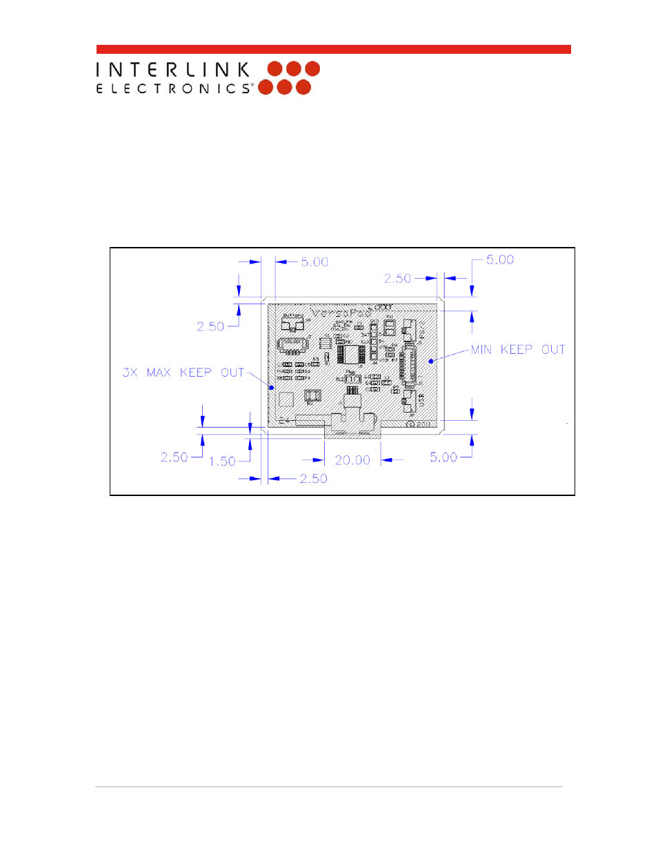
5.4 PCB Keep Out Area
The illustration below highlights the recommended keep out area for the mounting bracket or
other surrounding interfaces. The keep out area can be reduced as long as proper care and
tolerance studies are performed to avoid interference with components and interfacing
connectors. Also note that the interfacing geometry should be designed to avoid
interference with the sensor tail that wraps around the PCBA. Maximum component heights
can be found in the drawing in section 8. The 3D CAD model on our website is a useful tool
for packaging the VersaPad into your application.
Figure 8: Mounting Bracket & Keep out Area. Drawing is not to scale