Warning, Uc recessed wall mounting – First Co UC - Vertical front return with electric heat User Manual
Page 2
****** WARNING ******
On 1.5 and 2 ton units do not
use the blower low(red wire)
speed tap with electric resis-
tance heating. This could
cause overheating and a pos-
sible fire situation. High and
medium speeds keep hot spots
from forming. Follow supplied
wiring diagram strictly. Fail-
ure to do so will void all war-
ranties.
Does not apply to brushless DC
motors if so equipped. Follow
wiring diagram supplied.
ELECTRICAL
All wiring must comply with local and
national code requirements. Units are
provided with wiring diagrams and
nameplate data to provide information
required for necessary field wiring. Refer
to figure 2 for points of entry of the wiring
into the cabinet.
These units may be provided with a
Class 2 transformer for 24-volt control
circuits. Should any add-on equipment
also have a Class 2 transformer fur-
nished, care must be taken to prevent
interconnecting outputs of the two trans-
formers by using a thermostat with isolat-
ing contacts.
•
Always review the nameplate on each
unit for proper voltage and control con-
figurations. This information is deter-
mined from the components and wiring
of the unit and may vary from unit to unit.
•
When soldering or brazing to the unit,
it is recommended to have a fire extin-
guisher readily available. When solder-
ing close to expansion devices or other
components, heat shields or wet rags
are required to prevent damage.
•
When the fan coil unit is in operation
components are rotating at high speeds.
•
Units must be installed level to ensure
proper drainage and operation.
•
Check unit prior to operation to ensure
that the condensate water will drain to-
ward the drain connection. An overflow
drain or an auxiliary drain pan under the
fan coil may be required as a back up to
a clogged primary drain.
•
On units with plastic drain pans DO
NOT tighten more than hand tight.
•
Be sure that the drain pan is free from
foreign material prior to start up.
•
Check filter media installation to en-
sure that it is installed correctly. Use the
directional arrows or other information on
the filter to determine the proper flow
direction.
NOISE
These fan coil units are designed for
quiet operation, however, all air condi-
tioning equipment will transfer some
amount of noise to the conditioned
space. This should be taken into consid-
eration when planning the location of the
equipment.
COOLING COIL PIPING
These fan coil units are supplied with a
direct expansion refrigerant coil. The
suction and liquid lines must be sized in
accordance with the outdoor unit
manufacturer's recommendations.
****** WARNING ******
Do not touch any rotating
component with any object.
Damage to the equipment
and personal injury can
occur.
INSTALLATION
PRECAUTIONS
Installation of this fan coil should only
be performed by licensed personnel to
ensure proper installation and the safety
of the installer. The following are some
precautions to be followed for typical
installations.
•
Always use proper tools and equip-
ment.
•
No wiring or other work should be
attempted without first ensuring that the
fan coil is completely disconnected from
the power source and locked out. Always
verify that a good ground connection
exists prior to energizing any power
sources.
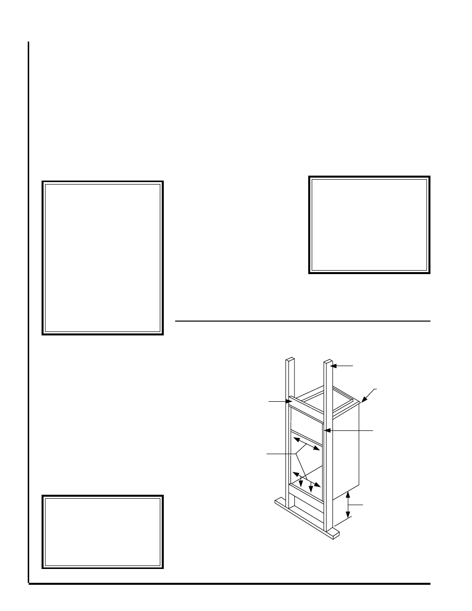
UC RECESSED WALL MOUNTING
CROSS MEMBER - TOP & BOTTOM
ATTACH UNIT TO FRAME USING
6 SCREWS / NAILS IN CABINET AT
LOCATIONS SHOWN
VERTICAL
2 X 4
BRACKET PLACEMENT
FOR HANGING
IN A CLOSET
UNIT FLUSH WITH
WALL STUDS
(NOT CRITICAL)
LEAVE SUFFICIENT
SPACE FOR DRAIN
PIPING
10" TO 12" MINIMUM
RECOMMENDED
SUPPORT FRAMING
Figure 1
****** WARNING ******
When connecting piping to
fan coil units, do not bend or
reposition the coil header tub-
ing for alignment purposes.
This could cause a tubing
fracture resulting in a refrig-
erant leak when pressure is
applied to the system.