Digital Alert Systems 627A User Manual
Model 627a stereo a/v switch instruction sheet
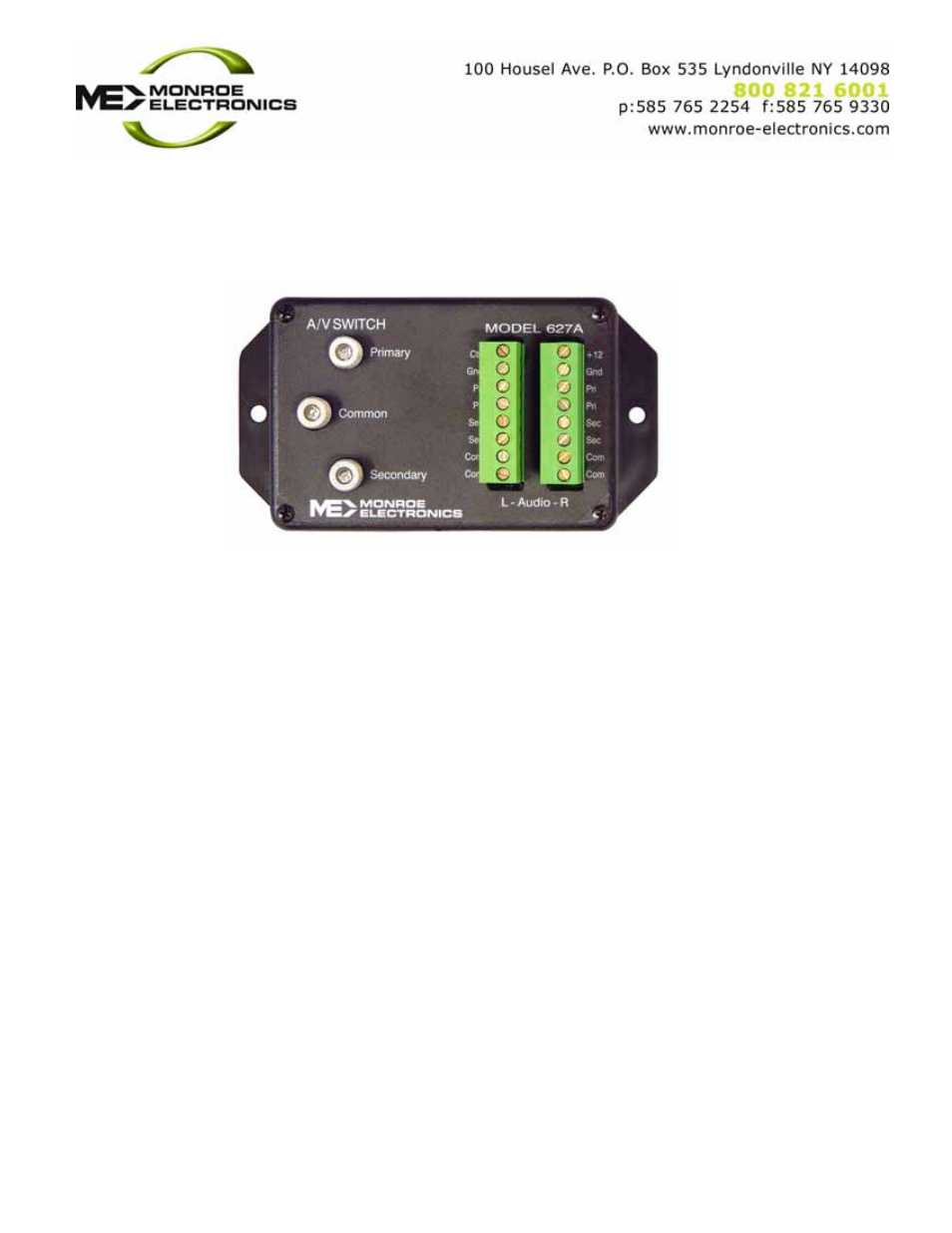
Model 627A Stereo A/V Switch Instruction Sheet
Installation
1. Connect your main
audio/video common outputs
to your equipment's' in-puts.
2. Connect the power supply
wires, White to +12 V and
Black to Ground, to the
terminal block connections
marked.
3. A TTL level control signal or
a dry contact across ground
and relay set will change the
output from the primary to the
secondary.
*Relay connection: Connect the
normally open (NO) contact to
Ctrl. Connect the relay common
(COM) contact to Gnd.
Open Collector:
Connect your transistor’s
Collector to Ctrl and the
transistor’s emitter to Gnd
Operation
The 627A’s primary inputs are
normally connected to the
common outputs. It remains in
this state until the Ctrl input is
connected to Gnd. This will
connect the secondary input to
common for the duration of the
connection.
Specifications
Video
75
Ω ; 'F' connectors
Audio
Balanced stereo; screw terminals
Video Isolation @ 950 MHz
> 52 dBmV
Video-IF/RF Return Loss
> 22 dBmV
Control Input
10 mA maximum to gnd.
Power Requirement
100-240 VAC
±2%,50/60 Hz.
Power pack output; +12 VDC
Physical
5.25"H x 2.75"W x 2"D
Design and specifications are subject to
change without notice.
P/N 1340169 (627A/100)
061109