11 operation, Figure 22 – United States Stove Company 5040 User Manual
Page 13
11
OPERATION
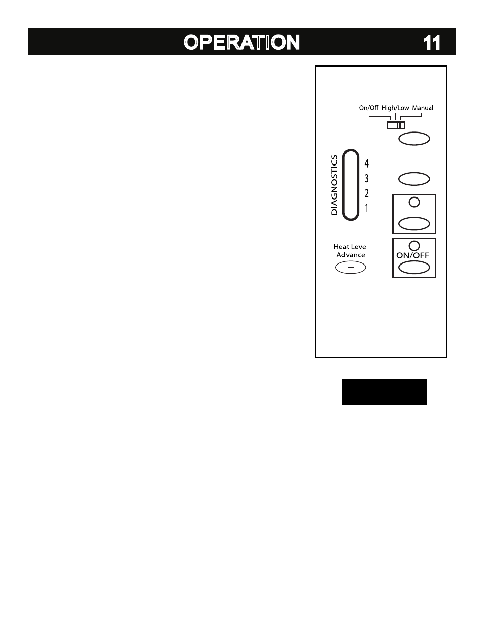
PANEL CONTROLS (See Figure 22)
The blowers and automatic fuel supply are controlled from a panel on the left-hand side of this
unit. The control panel functions are as follows.
a. ON/OFF SWITCH
• When pushed the stove will automatically ignite. No other firestarter is necessary. The
igniter will stay on for at least 10 and up to 15 minutes, depending on when Proof of Fire
is reached. The fire should start in about 5 minutes.
• The green light located above the On/Off button (in the On/Off box) will flash during the
ignition start-up period. (See figure 22)
• The Feed Rate Advance is inoperable during the ignition start period. When the red light
continuously stays on the Feed Rate Advance can be adjusted to achieve the desired
heat output.
NOTE: If the stove has been shut off, and you want to re-start it while it is still warm, the “on/
off” button must be held down for 2 seconds.
b. FUEL FEED SWITCH
• When the “Fuel Feed” button is pushed and held down the stove will feed pellets
continuously into the burnpot.
• While the stove’s auger system is feeding pellets the amber light (in the “Fuel Feed” box)
will be on. (See figure 22)
CAUTION: DO NOT USE THIS CONTROL DURING NORMAL OPERATION BECAUSE IT
COULD SMOTHER THE FIRE AND LEAD TO A DANGEROUS SITUATION.
c. HIGH FAN SWITCH
• The room air fan speed varies directly with the feed rate. The “HIGH FAN” switch overrides
this variable speed function. It will set the room air blower speed to high at any feed rate
setting.
• When the “HIGH FAN” button is pushed the room air fan will switch to its highest setting.
• When this button is pushed again the room air fan will return to its original setting based
on the Feed Rate Advance setting.
d. RESET TRIM
Different size and quality pellet fuel may require adjustment of the “1” feed setting on the Feed
Rate Advance bar graph.
This is usually a one-time adjustment based on the fuel you are
using. The “RESET TRIM” button when adjusted will allow for 3 different feed rate settings for
the
#1 feed setting only. To adjust simply push the “RESET TRIM” button while the stove is
operating at setting “1” and watch the bar graph.
• When the “1” and “3” lights are illuminated on the bar graph the low feed rate is at its
“lowest” setting. (approx. 0.9 pounds per hour)
• When the “1” light is illuminated on the bar graph the low feed rate is at its “normal”
setting.
• When the “1” & “4” lights are illuminated on the bar graph the low feed rate is at its
“highest” setting.
NOTE: When the stove is set on “1” the “reset trim” values will be shown on the Feed Rate
Advance bar graph. For example if the Reset Trim is set to its lowest setting every time the
stove is set to low the “1” and “3” lights will be illuminated on the bar graph.
e. HEAT LEVEL ADVANCE
• This button when pushed will set the pellet feed rate, hence the heat output of your stove.
The levels of heat output will incrementally change on the bar graph starting from level “1”
to “4”.
NOTE: When dropping more than 2 heat level settings (i.e. 4 to 1) push the ‘High Fan’ but-
ton and allow the room air fan to run at that setting for at least 5 minutes to prevent the stove
from tripping the high temp thermodisc. If the high temp thermodisc does trip see “SAFETY
FEATURES”.
CAUTION: THE “4” SETTING IS DESIGNED FOR TEMPORARY USE ONLY. IF USED FOR
EXTENDED PERIODS, IT CAN SHORTEN THE LIFE EXPECTANCY OF THE UNITS COM-
PONENTS. AVOID USE AT THIS SETTING FOR MORE THAN ONE HOUR AT A TIME.
FIGURE 22
Fuel Feed
High Fan
Reset Trim