Installation – United States Stove Company 1261 User Manual
Page 5
-5-
Installation
Place the heater on solid masonry or solid concrete. When the heater is
used on a combustible fl oor, use an Underwriters Listed fl oor protector.
Th
e fl oor protector must comply with UL Standards and have an R-value
of 2.0. Th
e base should extend under the stove, at least 16" beyond the
door side of the heater and should extend 2" beyond the fl ue pipe if it is
elbowed towards a wall. (Fig. 5).
1. Uncrate and/or unpack the heater, removing all packing material,
being careful not to dispose of the Parts Bag.
2. Open the front feed door and remove the parts from inside the stove.
You should fi nd the following: Hearth Plate (1); Solid Damper (1);
Lids (2); Pivoting Top (1); Lid Support (1); Parts Package (1) contain-
ing nuts, bolts, door handle, door latch and securing hardware; Legs
(4); Cast Iron Collar (1); Cast Iron Damper (1); Baffl
e Assembly (1);
Lid Lift er (1).
3. Place cardboard or other soft material adjacent to the stove and
carefully turn the stove onto its top side (bottom facing up).
4. Attach hearth plate to the front of the stove in its proper location.
5. Attach both rear and front legs to the stove. Tighten the nuts and
bolts securely. Th
e stove may now be CAREFULLY turned over to
stand on it's four legs.
6. Attach the baffl
e assembly and fl ue collar to the stove by inserting
the baffl
e studs thru the two holes located on the top of the rear of
the stove; place the fl ue collar over the studs and mount using the
proper nuts and washers. Place lid support and lid in position on
pivoting top. Place the slide damper in position on the top of the
hearth plate and under the feed door, and secure with screw in slot.
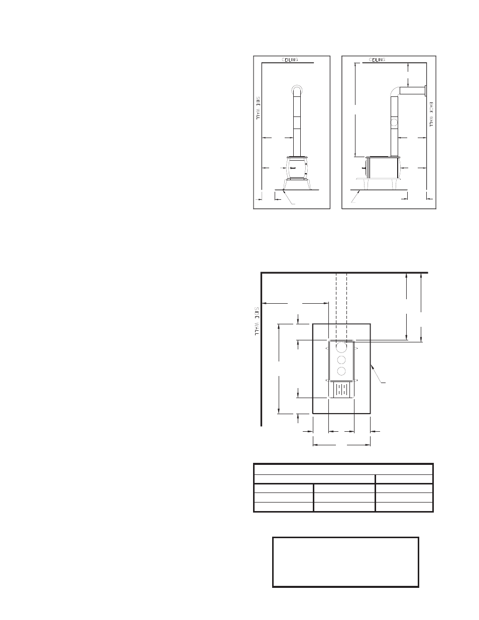
7. Aft er consulting the installation instructions for minimum clear-
ances to combustibles, locate your fl oor protector accordingly and
carefully place the stove in your selected location. Install stove pipe,
elbows and thimble as necessary, utilizing either a recently cleaned
and inspected masonry chimney (properly lined) or a UL Listed
chimney. Insure that the damper provided is installed in the fl ue
collar.
8. Again, check the following illustrations and be sure you have the clear-
ances shown from the heater and the connector pipe to combustible
surfaces. If you have a solid brick or stone wall behind your heater,
please consult your local building code for specifi c regulations that
may apply in your area. However, if the wall is only faced with brick
or stone, consider it a combustible wall.
9. If your chimney draft s excessively, purchase and use a Barometric
Draft Regulator (DR6 available from factory).
10. Th
e chimney connection should be as short as possible, and the
heater must have its own fl ue. Do not connect this unit to a chimney
fl ue serving other appliances.
11. Use three sheet metal screws in each stove pipe and or elbow joint
to fi rmly hold the pipe together. Seal around the screws
12. Do not install this heater in a mobile home or trailer.
13. Check your local building and insurance codes. Th
e installation
must comply with their rulings.
CAUTION!
KEEP FURNISHINGS AND OTHER
COMBUSTIBLE MATERIALS
AWAY FROM THE HEATER.
MINIMUM CLEARANCE
TO COMBUSTIBLE WALLS
HEATER/FLOOR PROTECTOR LOCATION
(Dimensions are required for non-protected surfaces.
See chart for dimensions for protected surfaces.)
Protected Surfaces (NFPA 211)
Parallel
Corner
Side
Rear
12-inches
12-inches
12-inches
305-mm 305-mm 305-mm
FLOOR
PROTECTOR
FLOOR
PROTECTOR
FIG. 2
(60"
MIN
.)
18"
FIG. 3
34"
865mm
26"
660mm
28"
712mm
28"
712mm
20"
508mm
37-1/2"
953mm
458mm
FLOOR
PROTECTOR
BACK WALL
DASHED LINES
SHOW STRAIGHT
OUT CHIMNEY
CONNECTOR
28"
60"
34"
865mm
26"
660mm
NON- COMBUSTIBLE
CONSTRUCTION IN
ACCORDANCE WITH
NFPA 211
FIG.
6"
153mm
6"
153mm
6"
153mm
16"
407mm
28-3/4"
730mm