Pin out table, Wiring schematic – Parr Instrument Primary Temp User Manual
Page 2
- 2 -
PTM Installation in a 4838
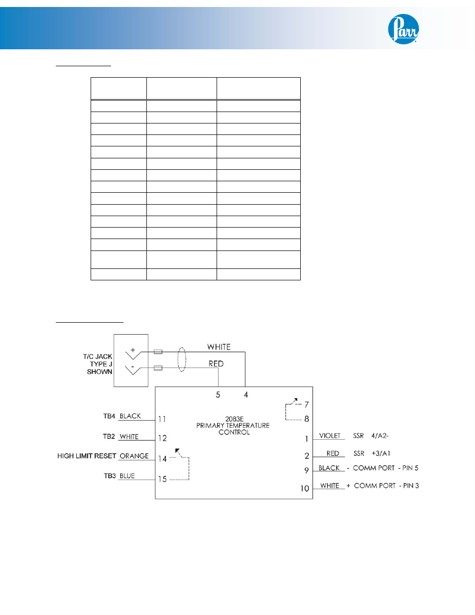
Pin Out Table:
2083E
Meter
Color: Attaches
to:
Pin 1
Purple
SSR 4/A2-
Pin 2
Red
SSR +3/A1
Pin 3
Red (RTD Only)
Thermocouple -
Pin 4
White*
Thermocouple +
Pin 5
Red**
Thermocouple - 1G
Pin 6
Pin 7
Pin 8
Pin 9
Black
COMM PORT - pin 5
Pin 10
White
COMM PORT - pin 3
Pin 11
Black
Terminal Block 4
Pin 12
White
Terminal Block 2
Pin 13
Pin 14
Orange
High Limit Reset - pin
2
Pin 15
Blue
Terminal Block 3
* White (Type - J), Yellow (Type - K), Blue (Type - T), Black (RTD)
** Red (Type - J, Type - K, Type - T), White (RTD)
Wiring Schematic