Switches and indicator lights – Lingenfelter L460135297 Lingenfelter LNC-TC1 Torque Cut Module RPM Limit v1.1 User Manual
Page 5
Page 4
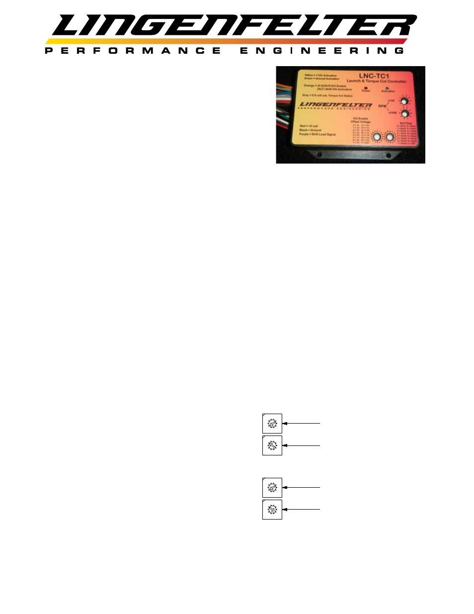
Switches and indicator lights:
Red (Power) LED:
•
Comes on solid on start-up (power on)
•
When active RPM is reached, red LED will blink (even if
activation wire is not triggered)
Green (Activation) LED:
•
slow blink rate (4 Hz) for Launch Activation only
•
medium blink rate (8 Hz) for torque cut (kill) Activation only
•
fast blink rate (16 Hz) for both launch and torque cut inputs on
Torque cut settings:
•
Controlled by two (2) 16 position switches: Kill Enable Offset Voltage and Kill Time
o Torque cut (kill) enable voltage
o Torque cut (kill) duration in milliseconds
Launch control settings:
•
Controlled by two (2) ten position switches (RPM)
o One ten position switches for selecting hundreds of RPM (x100)
o One ten position switches for selecting thousands of RPM (x1000)
Notes:
•
The LNC-TC1 RPM limiter function will not trigger at RPM levels below 1500 RPM
•
Changes to the switch point settings (RPM, Cut voltage, Cut duration) must be done with the
ignition off
o The switch positions are ONLY read on start up
Example settings:
•
1900 RPM activation point for launch control
o Upper (x100) RPM switch on position 9
o Lower (x1000) RPM switch on position 1
• 69
00 RPM activation point for RPM limiter
o Upper (x100) RPM switch on position 9
o Lower (x1000) RPM switch on position 6
• 0.4
Voltage activation point with 80 ms torque cut
o Kill enable offset voltage in position 2
o Kill time in position B
0
56
789
1234
0
56
789
1234
100's Switch (x100 RPM)
1000's Switch (x1000 RPM)
RPM Programming
Switches
0
56
789
1234
0
56
789
1234
100's Switch (x100 RPM)
1000's Switch (x1000 RPM)
RPM Programming
Switches