Labconco Purifie Horizontal Clean Benches 3970424 User Manual
Page 36
Chapter 6: Maintaining Your Vertical Clean Bench
Product Service 1-800-522-7658
32
32
Calibration
1. Ensure the flow switch and alarm circuit board are installed and
operational.
2. Allow the enclosure to operate for at least two minutes.
3. If factory installed, the monitor will alarm at 30±10 fpm downflow velocity
with the average outflow velocity set at 85±10 fpm.
4. To change the factory setting, set the downflow velocity to the desired
alarm condition using the speed control adjustment procedure outlined in
Chapter 6. Once the alarm condition is set, use a small screwdriver to turn
the adjustment screw on the airflow switch counterclockwise (facing the
screw) until the “low” airflow red LED lights and the audible flow alarm
sounds.
5. Adjust the downflow velocity to the nominal operating point required. The
green “safe” LED should light.
6. Over time the HEPA filter will load and eventually slow the downflow
velocity. Once the alarm condition is met, simply increase the speed
control as outlined in Chapter 6 or replace the HEPA filter if the speed
control is maximized.
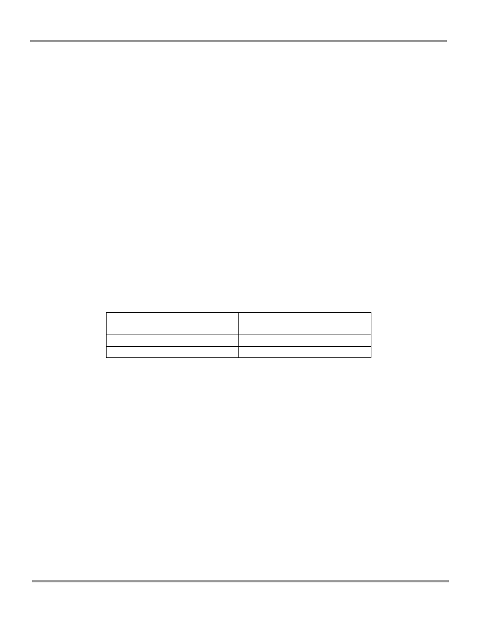
7. The table below lists typical alarm conditions based on normal operating
conditions. Typical alarm conditions are set at downflow velocities of 10
to 30 feet per minute below the normal operating conditions due to supply
air and exhaust air fluctuations, as well as room air cross drafts. Consult
your Safety Officer or Laboratory Manager for proper operating speeds.
Enclosure Operating
Downflow Speed
Alarm Condition Set Point
Speed
55 ± 10 fpm
25-35 fpm
45 ± 10 fpm
25-35 fpm
- Purifie Horizontal Clean Benches 3970423 Purifie Horizontal Clean Benches 3970421 Purifie Horizontal Clean Benches 3970420 Purifie Horizontal Clean Benches 3970404 Purifie Horizontal Clean Benches 3970403 Purifie Horizontal Clean Benches 3970401 Purifie Horizontal Clean Benches 3970400 Purifie Horizontal Clean Benches 3970324 Purifie Horizontal Clean Benches 3970323 Purifie Horizontal Clean Benches 3970321 Purifie Horizontal Clean Benches 3970320 Purifie Horizontal Clean Benches 3970304 Purifie Horizontal Clean Benches 3970303 Purifie Horizontal Clean Benches 3970301 Purifie Horizontal Clean Benches 3970300 Purifie Horizontal Clean Benches 3970224 Purifie Horizontal Clean Benches 3970223 Purifie Horizontal Clean Benches 3970221 Purifie Horizontal Clean Benches 3970220 Purifie Horizontal Clean Benches 3970204 Purifie Horizontal Clean Benches 3970203 Purifie Horizontal Clean Benches 3970201 Purifie Horizontal Clean Benches 3970200