Assembly instructions – Vogelzang BX22EL User Manual
Page 5
VGZ-003 / 20120224.1
BX22EL /
Page 5
ASSEMBLY INSTRUCTIONS
tools
required
materials
required
(NOTE: The following items are NOT included with your stove)
Screwdrivers
(blade and cross types)
5/16˝ Open End Box Wrench
5/16˝ Nut Driver or
Ratchet with 5/16˝ Socket (for
1/4˝ hex nuts)
11mm Nut Driver or Ratchet
with 11mm Socket (for stove
bolts)
Safety Glasses
Pencil
6 foot Folding Rule or
Tape Measure
Tin Snips
Drill: Hand or Electric
1/8˝ dia. Drill Bit
(sheet metal screws)
Flooring Protection: 28” x 51”
as specified (see page 6)
Connector Pipe: 6˝/152mm
dia. min. 24 MSG black or 26
MSG blue steel stove pipe or
elbow(s) required.
1/2˝ Sheet Metal Screws
Chimney: Existing 6˝/152mm
Lined Masonry Chimney or
6˝/152mm Inside Dia. Listed
Type HT chimney.
Furnace Cement (manufacturer
recommends Rutland Code 78
or equivalent)
continued on next page
NOTICE: Vogelzang International Corp. grants no warranty, stated or implied, for the installation or maintenance
of our wood stove and assumes no responsibility of any incidental or consequential damages.
3. Place flattened carton on floor and carefully turn
stove over onto carton.
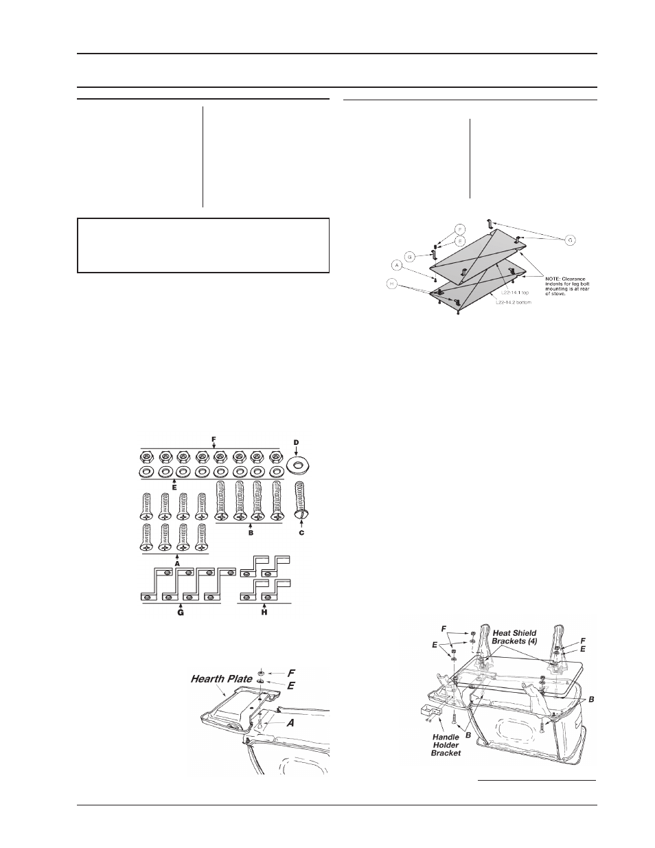
Figure 1 – Hardware Pack
Figure 2 – Hearth Plate
Assembly
Figure 4 –
Leg & Heat
Shield Assembly
4. Attach hearth to
bottom of stove,
figure 2, with two
short stove bolts
(A), washers (E),
and hex nuts (F).
5. Assemble the heat
shield, figure 3.
The notches in the
Figure 3 –
Heat Shield
Assembly
sides of the heat shield provide access to the rear
leg mounting bolts and need to be positioned to the
rear of the stove. The lower heat shield (L22-14.2)
is mounted to the four (4) separator brackets (H)
welded to the bottom of the top head shield (L22-
14.1). Mount the four (4) hanger brackets (G) to the
top of the upper heat shield.
6. The heat shield assembly (L22-14A) is held to the
stove with the mounting bolts for the legs, figure 4.
Note that one of the legs (L22-1b) has mounting
holes for the separable handle holder bracket and
this leg should be used as one of the front legs. The
long mounting bolts (B) pass through the clearance
holes in the base of the stove, figure 4, through the
legs, the heat shield hanger brackets (G) and then
are secured with washers (E) and hex nuts (F).
7. Attach the handle holder bracket (L22-18) to the
front leg (L22-01b) with the mounting holes.
8. Carefully lift stove upright and place in desired loca-
tion (see following instructions for properly locating
stove).
CAUTION: STOVE IS HEAVY. MAKE SURE YOU
HAVE ADEQUATE HELP AND USE PROPER
LIFTING TECHNIQUES WHENEVER MOVING
STOVE.
Refer to diagram and parts lists at back of this
manual.
1. Uncrate the stove and remove packing materials
and protective poly bag. (Save exterior cardboard
box for further assembly.)
2. Remove parts from inside of stove. Parts
include: one damper collar (22L-12), one feed door
(22L-07), one hearth plate (22L-06), separable
handle (22L-17A), four legs (22L-01 & 22L-01b),
two heat shield panels (22L-14.1top & 22L-14.2
bottom) and hardware pack (22L-HP) from inside
firebox.