Intek 100CS User Manual
Page 4
- 2 -
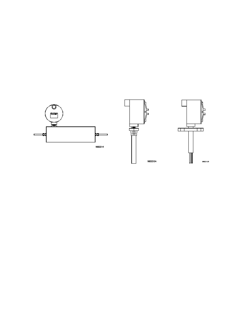
Example of dual probe
with flange fitting
Example of single probe
with NPT fitting
Nonintrusive transducer
(TU)
1.2 DESCRIPTION OF OPERATION
Rheotherm flow switches are available with various nonintrusive and intrusive transducer designs, but
they all use the same thermal sensing technique. Two temperature sensors are used
one is in thermal
equilibrium with the fluid and provides a fluid temperature reference, while the second temperature
sensor is located near a heater so that its temperature is slightly above that of the fluid. In a TU
transducer, the temperature sensors and heater are attached to the outside of the flow tube, whereas the
dual and single probe transducers have the sensors and heater located in the probe(s) that are inserted
into the stream. The amount of heat removed from the heated sensor by the stream is related to fluid
velocity. Hence, the measured temperature differential between the reference sensor and heated sensor
is a function of flow rate. Only Intek, Inc. is licensed to use this patented and trademarked method for
precision flow measurement.
1.3 PRECAUTIONS
1.
Use proper input power
Check the label on the unit for the input power requirements.
2.
Use reasonable care in handling the flow switch. Do not try to disassemble the transducers;
there are no removable parts.
TU excessive twisting or bending can damage the sensor. The flow tubes are thin-walled
tubing.
Probes (NPT/2I, NPT/I, BF/2I, BF/I, etc.) take care not to bend the probes or damage the
tips. Do not try to remove or turn the electronics box.
3.
Check the flow switch maximum temperature rating
do not operate a transducer at or
subject it to a temperature above its specified limit.
4.
Keep moisture out of the electronic enclosure. Once cable connections are made in the
electronic box, make sure the lid is tightly closed. Seal conduit lines if they can become wet
inside.
5.
Keep transducer wetted surfaces clean and free of permanent layer build-up.