Fhcommander_4, Inflating instructions, Hardware features – Advanced Elements FH302 User Manual
Page 4
Use either a bellows style foot pump or two-way hand pump to inflate your boat.
Be sure that the fitting on the pump hose fits snug in the valves on the boat.
NEVER USE COMPRESSORS, CO2, OR COMPRESSED AIR AS THEY
MAY DAMAGE YOUR BOAT.
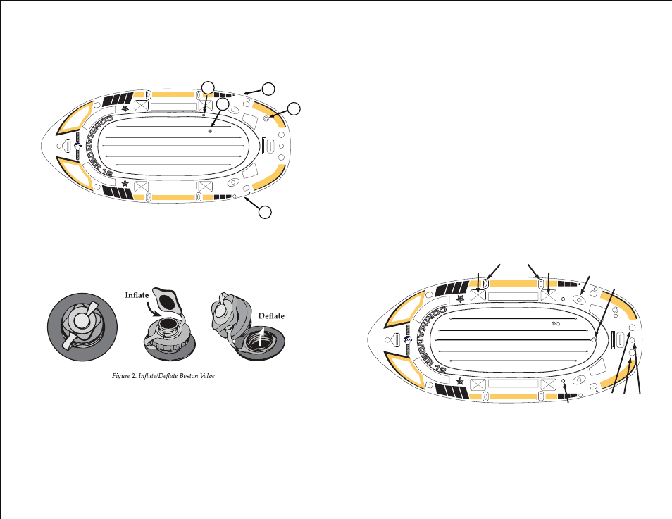
2.1 Understanding Your Valves
1. The Commander uses standard Boston valves for inflation of the Main
Air Chambers (Marked as 1 and 5). The following figures give details on
how to operate these valves.
2.2 Inflation
Inflate your boat in the following order: FAILURE TO FOLLOW THESE
INSTRUCTIONS MAY CAUSE DAMAGE TO YOUR BOAT. DO NOT OVER
INFLATE.
1. Inflate Chamber 1 until it feels firm to the touch.
2. Inflate Chamber 2, “floor”, (using appropriate fitting). Fill with air until firm.
CAUTION: Do Not Over Inflate. The floor should still be a little soft, not
rock hard.
3. Inflate Chamber 3 and 4 until they protrude from the underside of the boat and
become firm.
2. INFLATING INSTRUCTIONS
Figure 1. (5 CHAMBERS)
Figure 3.
1. Inner Main Chamber
2. Floor Chamber
3. Side Stabilization Chamber
4. Side Stabilization Chamber
5. Outer Main Chamber
3. HARDWARE FEATURES
4. Inflate Chamber 5 until it feels firm to the touch.
5. Inflate the seats until firm. CAUTION: Do Not Over Inflate.
IMPORTANT:
DO NOT OVER-INFLATE THE BOAT. OVER-INFLATION IS THE
PRIMARY CAUSE OF DAMAGE. INFLATE THE BOAT UNTIL MOST OF
THE WRINKLES ARE GONE OR UNTIL IT FEELS FIRM TO THE
TOUCH.
CAUTION: Water temperature and weather will affect the air pressure of the
boat. In cold weather your boat will lose some pressure as the air inside
contracts. If this occurs, you may want to add a bit more air to improve your
boat's performance. However in hot weather, or prolonged direct sunlight, the
air inside will expand. You must let some air out of the appropriate chambers to
prevent the boat from failing due to overpressure. You should avoid exposing
your boat to extreme temperatures (hot or cold).
W
A
R
N
ING
USE ON
LY IN PR
O
TE
C
TE
D
W
ATERS
TO
W
ITHIN 300M OF
THE SHORE
1
3
5
4
2
4
Valve
for S
tabil
izatio
n Ch
amb
er
locat
ed on
bott
om s
ide
3
Val
ve
fo
r S
tab
ilizat
ion
C
ham
ber
loca
ted
o
n b
ott
om
sid
e
The following illustration has been provided to asist you in identifying some of
the more important hardware features located on your boat.
W
A
RNIN
G
USE ON
LY IN PRO
TECTED
W
ATERS
TO
WITHIN 300M OF
THE SHOR
E
2
5
4
Valve
for S
tabiliz
ation
Chamber
locat
ed on bo
ttom side
3
Val
ve f
or
Sta
bili
zat
ion
C
ham
ber
lo
cat
ed
on
bo
tto
m s
id
e
Oar Holders
Fishing Rod
Holder
Swivel
Oarlock
Swivel
Oarlock
Drain Plug
Motor Mount
Fittings
Motor Mount
Fitting