Holtgreven Portable Axle Scale 7'x10' Scale Only User Manual
Page 2
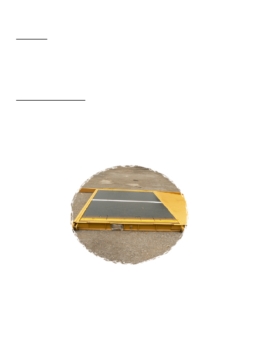
GENERAL
This scale system must be installed on a firm and level surface. Particular attention should be paid to the load
bearing points at the end of each module. Note that if the area between the ends of the scale is too high it will
cause weight errors by rocking the sub-frame. The same condition can be created if surface settling occurs, the
center of the frame will not compress the surface at the same rate as the load bearing ends. This will create the
same bind as the unleveled surface described above.
INSTALLATION STEPS
1.
Site preparation. You should have a firm and level surface area that is at least one (1) foot wider and five
(5) feet longer than the overall dimensions of the scale. For a temporary installation compressed stone is
adequate. For any installation over 6 months it is recommended that concrete footers be poured below frost
level.
2.
Determine where your indicator will be installed and arrange the scale so the J-Box is located on the
same side. Note that the J-Box is located under the access plate on one side of the deck plate. In the center of
the length.
3.
Set the first module. Lifting points are provided on the four corners of the scale frame.