Imperial Tools 700-F User Manual
Page 6
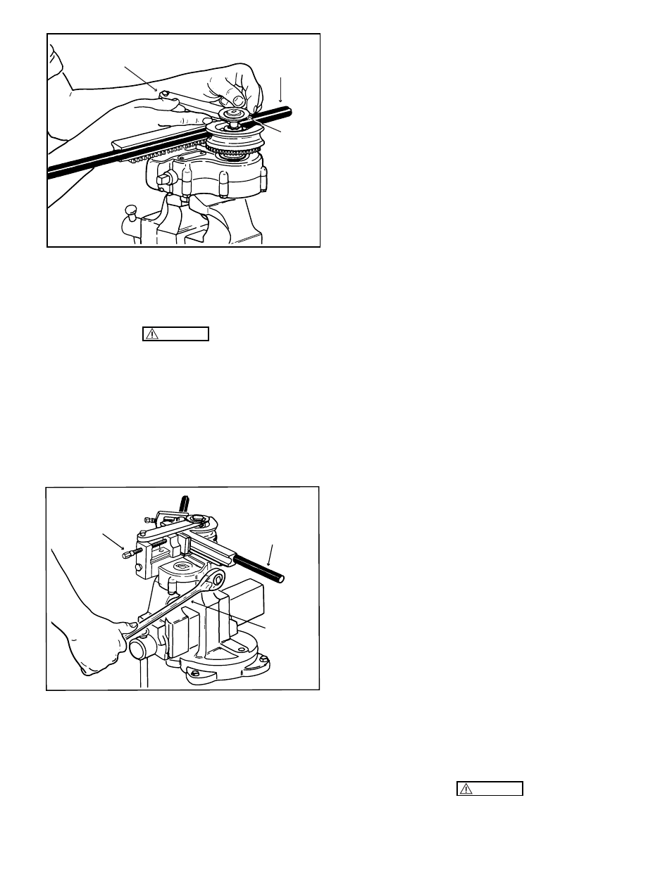
Figure 11. Forming a Bend with Tube Bender
Clamped in a Vise
b. While the ratchet handle is being operated, the form
block rolling against the form shoe will bend the tube to the
same radius as the groove in the form block. Before begin-
ning the bend, determine the angle of bend desired and
operate the ratchet handle until the dial indicates the pre-
determined degree of bend. When the tubing is released
from the tube bender,
Ordinary cup grease and similar lubricant
there will be a small amount of "spring-back"; the actual
amount varying in proportion to the hardness and
elongation characteristics of the tubing. This "spring-back"
will also increase the diameter of the bend slightly.
Experience will best determine the exact amount of
"spring-back" and dictate the amount of over-run required
in order to anticipate the exact degree of bend acquired
after the tubing is released.
NOTE
Lubricants are neither required nor recommended
on any of the parts during bending operations.
c. When bending is complete, remove the ratchet handle,
loosen the feed screw and lift the tension yoke straight up
until free of the drive shaft. Rotate the tension yoke to one
side and remove the form shoe from the tube bender.
Release the tube from the form block by loosening the screw
in the clamp yoke.
NOTE
After finishing with the equipment, pack all parts
in the carrying case to prevent misplacement of
components.
14. MAINTENANCE.
15. The tube bender and accessories are calculated for
stresses well in excess of any stress that will be encountered
in actual tube bending operations. As a result, very little
maintenance should be required at any time, provided the
external components are kept free of dust and grit which
would produce excessive wear on the parts.
16. CLEANING.
17. Dust, dirt and other foreign material should not be
permitted to collect on the feed screw, pressure plate, form
shoe, slide block and other exposed parts of the machine.
Foreign material should also be wiped off form blocks, form
shoes, rack and sector gears before beginning any bending
operation. Remove foreign material with a stream of
compressed air, aided by a soft bristle brush if particles are
difficult to dislodge. Wipe all parts including the housing
occasionally with a clean cloth. If grease and other
stubborn accumulations are present on the parts, wet the
cloth with naphtha or dry cleaning solvent, Federal
Specification P-S-661b.
18. LUBRICATION.
19. All bearings, gears and parts located inside the housing
are lubricated during assembly by packing gear teeth with
extreme-pressure, low-temperature grease, Specification
MIL-G-7118, or equivalent. No lubrication is required
except when the tube bender proper is disassembled for
repairs, at which time the old grease should be removed by
washing in dry cleaning solvent, Federal Specification P-S-
661b, and repacking with fresh grease of the above specifi-
cation, or equivalent.
6
CAUTION
Figure 10. Engaging the Tension Yoke and Dial
13. BENDING PROCEDURE.
k. After engaging the dial, tighten the feed screw securely
to force the faces on the form shoe against the faces on the
form block. (See figure 9.)
Make sure the teeth on the rack are meshed with
the teeth on the sector gear before tightening the
feed screw.
a. Engage the ratchet handle with the square end of the
shaft which protrudes from the side of the housing. Rotate
the shaft in a clockwise direction. (See figure 11.)
CAUTION
DIAL
TUBE
TENSION YOKE
TUBE
FEED SCREW
RATCHET
HANDLE