Sony SAT-A2 User Manual
Page 80
Attention! The text in this document has been recognized automatically. To view the original document, you can use the "Original mode".
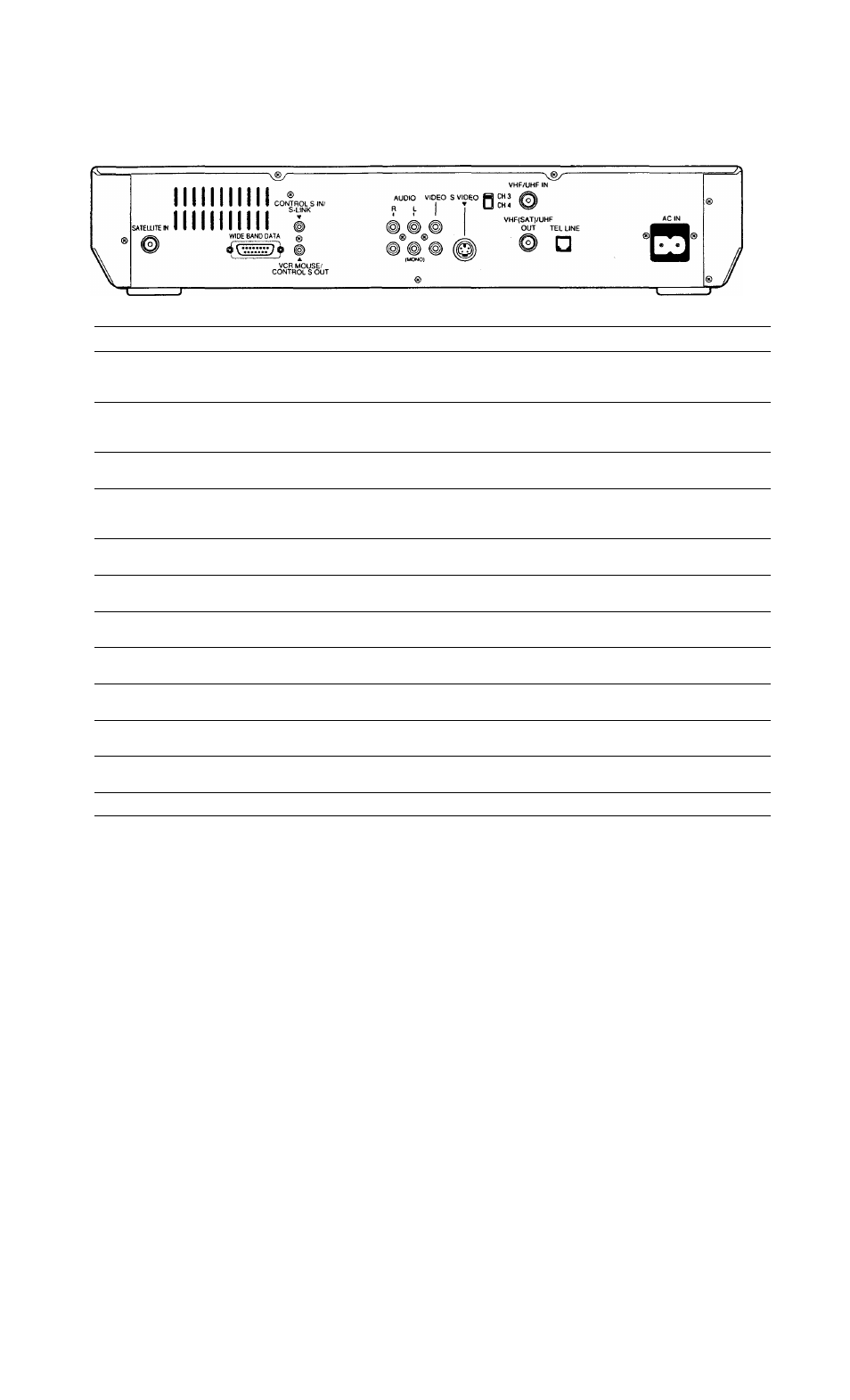
Back Panel (SAT-B2)
Connector
Description
Cable Type
SATELLITE IN
Connects to the LNB on the satellite antenna.
Solid Bare Copper
RG-6 Coaxial
(75-ohm / F-type)
WIDE BAND DATA
Allows you to connect your DSS receiver to new technologies
(such as high-definition television), as they are introduced.
Additional accessories may be required.
Depends on future
applications
(D-sub 15 pin)
CONTROL'S IN/
S-LINK
Allows you to pass on remote control signals to another Sony
infrared-controlled audio or video component.
Audio mono
miniplug
VCR MOUSE/
CONTROL'S OUT
Allows you to pass on remote control signals to another Sony
infrared-controlled audio or video component. Also used to
connect the Sony VCR Mouse (RM-VMlOl).
Audio mono
miniplug
AUDIO (R)/(L)
OUT
Connects your DSS receiver to the right and left audio inputs of
your audio or video component.
Audio (2)
(RCA-type)
VIDEO OUT
Connects your DSS receiver to your TV or VCR's video input. Video
(RCA-type)
S'VIDEO OUT
Allows you to connect your DSS receiver directly to your TV (if
your TV has S-VIDEO IN).
S-Video
(4-pin mini DIN)
CH3/CH4 Switch
When you use an RF connection, this setting determines the TV
channel on which programs from the DSS receiver can be viewed.
VHF/UHF IN
Allows you to connect your DSS receiver to your normal
(terrestrial) TV or cable TV service.
RG-59 Coaxial
(75-ohm/F-type)
VHF(SAT)/UHF OUT
Connects to vour TV or VCR.
RG-59 Coaxial
(75-ohm/F-type)
TEL LINE
Connects your DSS receiver to a telephone jack. This allows you to
order pay-per-view programs.
Telephone (RJ-11)
AC IN
Connects your DSS receiver to a 120V AC outlet.
AC
80
Appendix: Other Information