Craftsman 486.246231 User Manual
Page 6
6
FIGURE 4
STEP 5:
(SEE FIGURE 4)
•
Place plug (D) on a work bench or solid table and
push end of bumper down onto plug. Repeat for all
four plugs.
PLUG (D)
BUMPER
PUSH DOWN
WITH EVEN
PRESSURE
WORK BENCH
OR SOLID TABLE
FLAT
WASHER
(I)
LOCK
WASHER
(H)
BOLT
(C)
LEFT MOUNTING
BRACKET
BUMPER STOPS
FACE OUT
ALIGN THESE HOLES
ATTACH TO
THIS HOLE
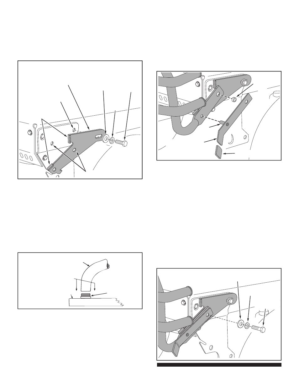
STEP 4:
(SEE FIGURE 3)
•
Attach left mounting bracket to hole shown in left side
of tractor frame using bolt (C), lock washer (H) and
fl at washer (I). Align middle hole in bracket with empty
hole in tractor frame and tighten bolt (C) to hold
bracket in place. Re peat for right mount ing bracket.
FIGURE 3
LEFT SIDE VIEW
(GT) FRAME SHOWN
STEP 6:
(SEE FIGURES 5 AND 6)
• Assemble plastic grips (F) onto locking levers.
• To attach bumper to tractor:
1. Place fl attened ends of bumper onto mounting
brackets. Insert pin of locking lever through front
hole in bumper and into front hole in mounting
bracket to support bumper on mounting bracket.
2. Insert pivot spacers (E) into rear holes in bumper.
FIGURE 5
LEFT SIDE VIEW
PIVOT
SPACER
(E)
PIN
LOCKING LEVER
GRIP (F)
3. Fasten locking lever and bumper to mounting bracket
using a screw (A) or bolt (B), a lock wash er (H) and a
fl at wash er (I). Use screw (A) for LT tractors and bolt
(B) for GT tractors. Assemble screw or bolt through
pivot spacer in rear hole in bumper and into tractor
frame.
Tight en. Re peat for other side.
NOTE: If hole in (LT) tractor frame is not thread ed, push
in while turning screw (A) to create threads in hole.
IMPORTANT: You must lower bumper before raising tractor
hood. Pull out on lock ing levers and push bumper down as
far as it will go.
FLAT
WASHER (I)
LOCK
WASHER (H)
SCREW (A)
or BOLT (B)