Installation – Great Plains CDS-JohnBlue NGP Series Pumps User Manual
Page 5
© 2013 CDS-John Blue Co.
5
INSTALLATION
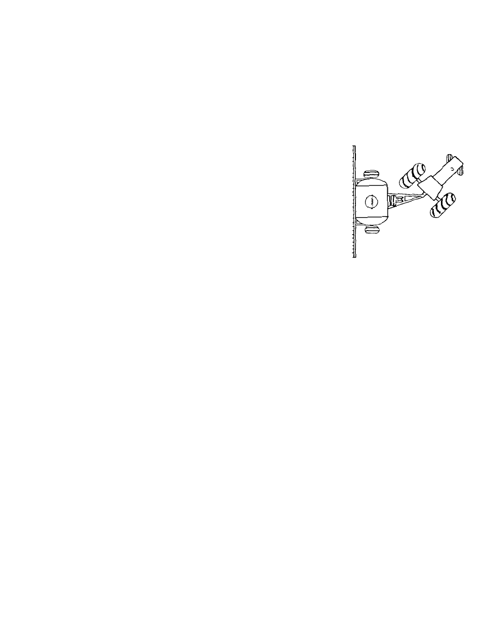
MOUNTING
The NGP pump should be mounted on a rigid base in a horizontal position.
The mount position should allow for a straight drive chain and proper tightness.
Chain idlers should be installed on the slack side of the drive chain.
The supplied rubber washers are installed between the pump and mount.
Caution should be exercised on implements with wings or folding members to assure that sufficient area is
allowed around the pump and plumbing to not cause contact or binding.
Verify that the rear tractor wheel will clear the pump during sharp turns.
The oil vent plug should be installed in the oil fill located on top of crankcase.
SUCTION PLUMBING
An adequately sized 30 mesh strainer should be installed on the suction side of
the pump and should be checked at each tank filling for debris, which could
cause suction restriction, starving the pump of flow.
The NGP pump does produce suction to pull fluid from the tank; however, it is
recommended to mount the pump level or below the tank, if possible, to assure the most effective and
quickest prime.
Install the process fluid suction line as straight as possible avoiding restrictions from kinks or extremely
sharp turns. This will ensure even flow during maximum pump output.
Quick connect fittings should be checked and double checked to verify that no leakage is present. Quick
connects, although commonly necessary, quite often can produce a suction leak if installed in a bind
allowing air to enter the pump, causing loss of prime and / or reduction in pump output.
It is recommended that suction line hoses be double clamped. Again, this is an area that can produce a
suction air leak into the pump, even if no drip from the hose is present.
DISCHARGE PLUMBING
It is not recommended to install a discharge strainer as these could clog with debris causing significant
discharge pressure and possible system damage in positive displacement pump applications.
Flow dividers may be installed either directly on top of the discharge port or remote mounted.
Orifice applications must pay particular attention for proper orifice sizing for the specified application rate.
It is recommend that applications using a double piston pump with two flow dividers remove the common
manifold and plumb each flow divider independently to each piston to assure accuracy.
On – The – Go Variable Rate applications require that a CDS – John Blue Co. flow divider distribution
manifold be used that will automatically and accurately adjust for varying on the go rate changes.
WARNING: The flow range of a NGP pump far exceeds the flow curve of a single orifice operating below
120 psi. For Example: An orifice application at 30 psi discharge pressure for a rate of 20 GPA @ 4 mph will
produce 422 psi when the rate is adjusted to 50 GPA and ground speed increased to 6 mph.