Combination clutch/brake, Clutch/brake selection, Application data – Wichita Clutch CCB - Combination Clutch Brake Unit User Manual
Page 3: Selection
Combination Clutch/Brake
12
Wichita Clutch 800-964-3262
P-1100-WC 1/12
Clutch/Brake Selection
A typical Combination Clutch/Brake application
would be on a geared punch press. To properly
select a CCB the fol low ing application
information is needed.
1. To determine the proper Application Duty
Factor for a Geared Punch Press, consult
page 16. Under Duty “B” or Normal, the
Duty Factor is 1-1/2.
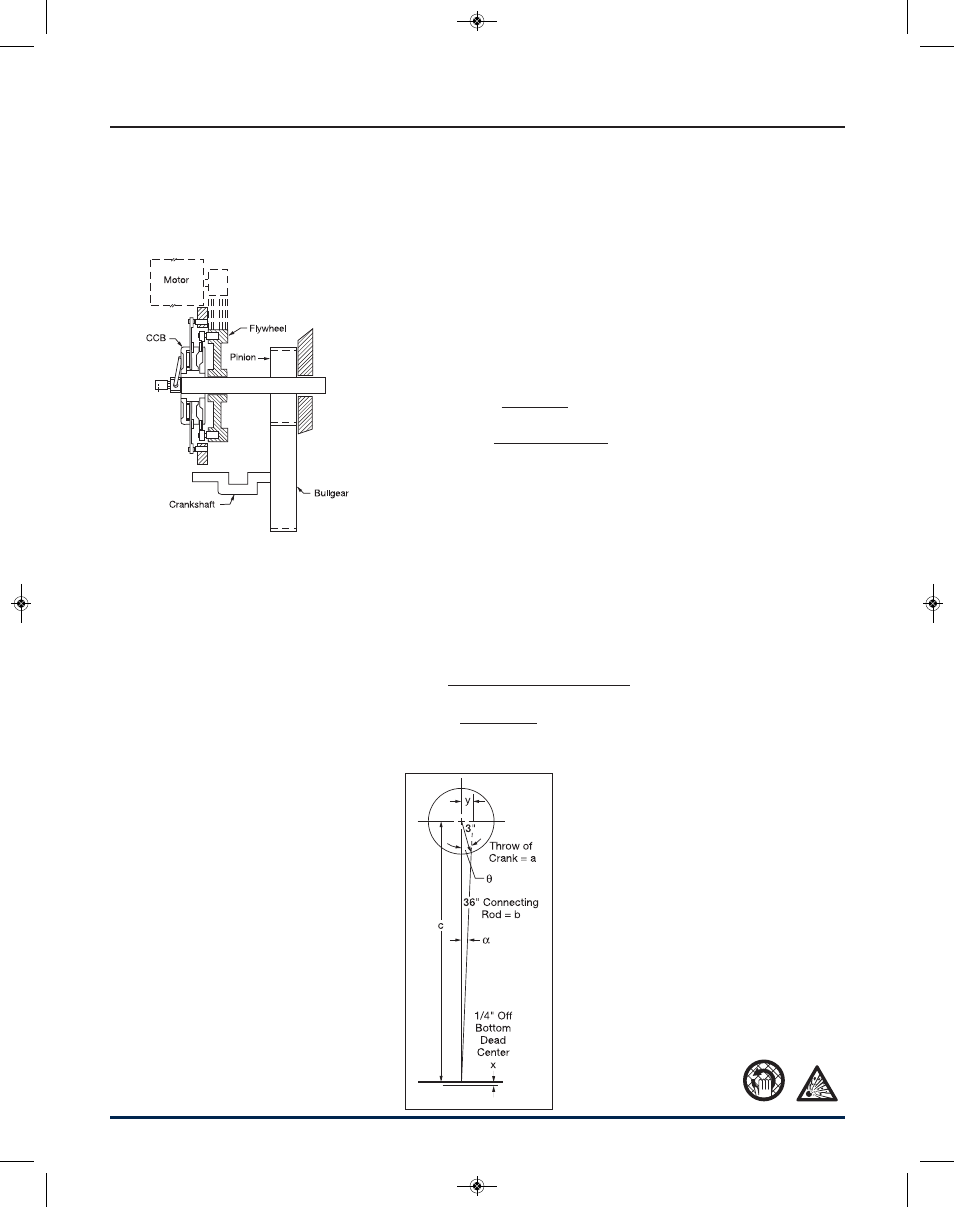
2. To determine the application clutch torque,
the following information is needed:
a. Torque @ Crank
= (Rated Tonnage) (2000 lb./ton) (Torque
Arm)
b. Torque Arm = y = (c) (tan a)
c = a + b - x
= 3 + 36 - .25
= 38.75 in.
b
2
+ c
2
- a
2
Cos
α
=
2bc
(36)
2
+ (38.75)
2
- (3)
2
=
(2) (36) (38.75)
= .99948
= 1.8478°
c. Torque Arm = y = (c) (tan
α
)
= (38.75) (tan 1.8478)
= (38.75) (.03226)
= 1.25 in.
Torque @ Crank
= (Rate Tonnage) (2000 lb./ton)(Torque Arm)
= (200) (2000) (1.25)
= 500,000 lb.in.
Required Torque @ Clutch
(Torque @ Crank) x (Crank shaft RPM)
=
lb.in.
Clutch Shaft RPM
(500,000) (30)
=
lb.in.
204
= 73,529 lb.in.
Application Data
Press Type . . . . . . . . . . . . Geared Punch Press
Rated Tonnage . . . . . . . . . . . . . . . . . . 200 tons
Crankshaft Speed . . . . . . . . . . . . . . . . 30 RPM
Degrees of Crank to Start . . . . . . . . . . . . . . 90°
Distance Above Bottom – x . . . . . . . . . . .25 in.
1/2 of Press Stroke (throw) = a . . . . . . . . . 3 in.
WR
2
of Parts on Backshaft . . . . . . . . . 78 lb.ft.
2
Required Clutch Torque. . . . . . . . . 73,529 lb.in.
Stroke . . . . . . . . . . . . . . . . . . . . . . . . . . . . 6 in.
Clutch/Brake Shaft . . . . . . . . . . . . . . . 204 RPM
Degrees of Crank to Stop . . . . . . . . . . . . . . 120
Connecting rod length = b . . . . . . . . . . . . 36 in.
WR
2
of Parts on Crankshaft . . . . . 39,091 lb.ft.
2
Cycles/Minute . . . . . . . . . . . . . . . . . . . . . . . . . 7
Air Pressure Available. . . . . . . . . . . . . . 100 PSI
Shaft Size . . . . . . . . . . . . . . . . . . . . . . . . 4.5 in.
Selection
Press clutch and brake selection is
based on:
1. Application Duty Factor
2. Application clutch torque
3. Application brake torque necessary
to stop
4. Maximum Energy Input
5. Heat generated during cycling
6. Bore size
1/4" distance
above bottom
WE9289 P1100WC PCB Catalog v4_NEW_P-1100-WC.qxd 1/31/12 10:51 AM Page 12