HF scientific MicroTUV Online UV %Transmission Sensor/Sampler (small) User Manual
Page 11
2.3.
2.3.
2.3.
2.3.
2.3.2
2
2
2
2
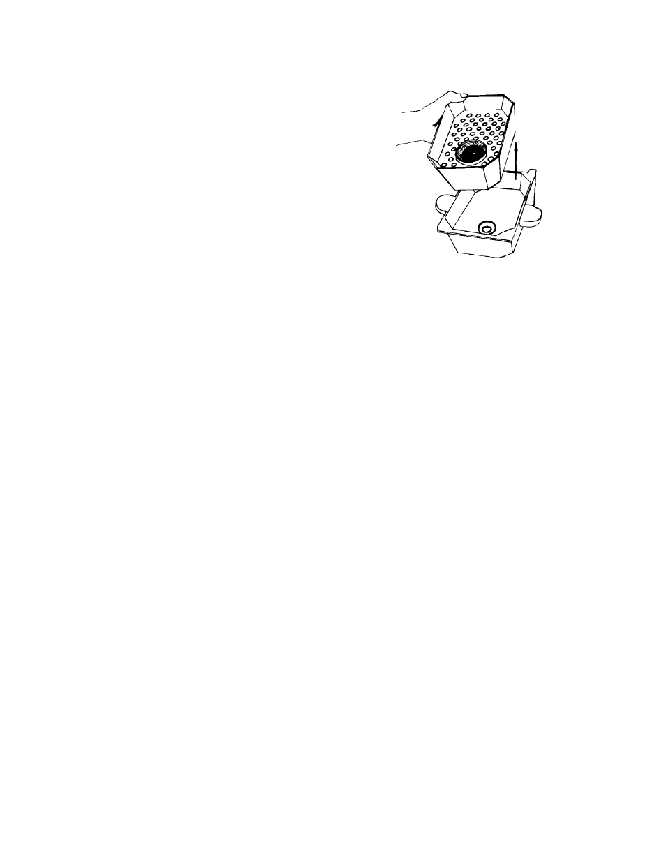
Removing and Installing the Desiccant Tray
Removing and Installing the Desiccant Tray
Removing and Installing the Desiccant Tray
Removing and Installing the Desiccant Tray
Removing and Installing the Desiccant Tray
Before operating the unit for the first time, the desiccant tray,
foot valve and O-rings must be installed in the sensor housing.
These items are shipped in a moisture resistant pouch. Use care
when opening so as not to damage the contents. The smaller O-
ring #205 goes into the desiccant tray, at the foot valve seat. O-
ring #218 goes underneath the desiccant tray in the O-ring
groove provided in the housing. Refer to figure 1 for details. See
section 6.4 for maintenance instructions.
2.3.
2.3.
2.3.
2.3.
2.3.3
3
3
3
3
Sensor/Sampler Plumbing
Sensor/Sampler Plumbing
Sensor/Sampler Plumbing
Sensor/Sampler Plumbing
Sensor/Sampler Plumbing
There are two external connections required. The first is the source line with the strainer at its foot. The second
is the drain line. These hoses are shipped in separate plastic bags in the Sensor/Sampler enclosure. The source
and drain lines should not exceed 25 feet (7.6 m) in length. The flow rate may be substantially reduced if the
lines are extended any further. The sampling flow rate is 140 ml/min. - 180 ml/min.
NOTE:
NOTE:
NOTE:
NOTE:
NOTE: Only route drain line to a free flowing drain.
Only route drain line to a free flowing drain.
Only route drain line to a free flowing drain.
Only route drain line to a free flowing drain.
Only route drain line to a free flowing drain.
NOTE:
NOTE:
NOTE:
NOTE:
NOTE: Only use as much line as needed. The excess should be cut off.
Only use as much line as needed. The excess should be cut off.
Only use as much line as needed. The excess should be cut off.
Only use as much line as needed. The excess should be cut off.
Only use as much line as needed. The excess should be cut off.
If any of the above conditions are not met, a flow error or an emergency drainage may occur.
2.4
2.4
2.4
2.4
2.4
COLD WEATHER
COLD WEATHER
COLD WEATHER
COLD WEATHER
COLD WEATHER KIT
KIT
KIT
KIT
KIT INSTALLATION
INSTALLATION
INSTALLATION
INSTALLATION
INSTALLATION
2.
2.
2.
2.
2.4.1
4.1
4.1
4.1
4.1
Heating Cable Installation
Heating Cable Installation
Heating Cable Installation
Heating Cable Installation
Heating Cable Installation
Disconnect power before installing the heating cable. The drain and intake lines must be sized to the proper
length before installing the heating cable. First, measure the amount of heating cable necessary to run from the
heating cable bulkhead on the bottom of the Sensor/Sampler enclosure to 2 inches above the maximum level of
the effluent stream and add 9 inches (230 mm) for the connections inside. If the heating cable needs to be cut
to length, make the cut at the open end, not the yellow sealed end. Next, prepare the cut end for connections
(see Figure 6). After the cable is prepared, unscrew the compression nut on the heating cable bulkhead on the
bottom of the instrument enclosure located between the intake and drain bulkheads (see Figure 7). Remove the
slotted through plug, it will be used later. Replace the compression nut, but do not tighten. Remove the cover of
the vertical wiring duct by pressing the fingers on the sides inward. Locate the heating cable power block (labeled
L3 & L4). The heating cable should now be stripped and prepared for power and ground connection at one end,
and sealed at the other. Feed the prepared end carefully through the bulkhead far enough to make the power and
ground hookup (about nine inches). Connect the power wires to the power block and the rolled braided shield wire
to the ground terminal block (see Figure 4). Run the heating cable into the wiring duct and through the fingers so
there are no kinks or slack in the cable. Replace the wiring duct cover. Unscrew the compression nut and allow
it to slide down the cable a few inches. The slotted through plug should be slit on one side to allow it to be wrapped
around the heating cable. Wrap it around the cable with the chamfered end down just below the bulkhead fitting.
Slide the plug into the bulkhead and tighten the compression nut behind it by hand. A wrench should not be
necessary.
Refer to Figures 4, 6 and 7.
TUV (01/03)
Page 3
REV. 2.2
Figure 1
Desiccant Tray Installation
WARNING:
WARNING:
WARNING:
WARNING:
WARNING:
If the power connection is to be hardwired, place
If the power connection is to be hardwired, place
If the power connection is to be hardwired, place
If the power connection is to be hardwired, place
If the power connection is to be hardwired, place TUV
TUV
TUV
TUV
TUV on a separate circuit breaker or
on a separate circuit breaker or
on a separate circuit breaker or
on a separate circuit breaker or
on a separate circuit breaker or
switch to allow for service. Observe all local wiring codes. Site connections should be wired by a Qualified
switch to allow for service. Observe all local wiring codes. Site connections should be wired by a Qualified
switch to allow for service. Observe all local wiring codes. Site connections should be wired by a Qualified
switch to allow for service. Observe all local wiring codes. Site connections should be wired by a Qualified
switch to allow for service. Observe all local wiring codes. Site connections should be wired by a Qualified
Electrician.
Electrician.
Electrician.
Electrician.
Electrician.