Using the dacs freque ii, Installation 1 connecting the power, 2 control voltage inputs – DACS Audio FREQue II User Manual
Page 4: 3 outputs from internal oscillators, 4 module8or input, Set for 240vac, Set for 110vac
Using the DACS FREQue II
Installation
1 Connecting the Power
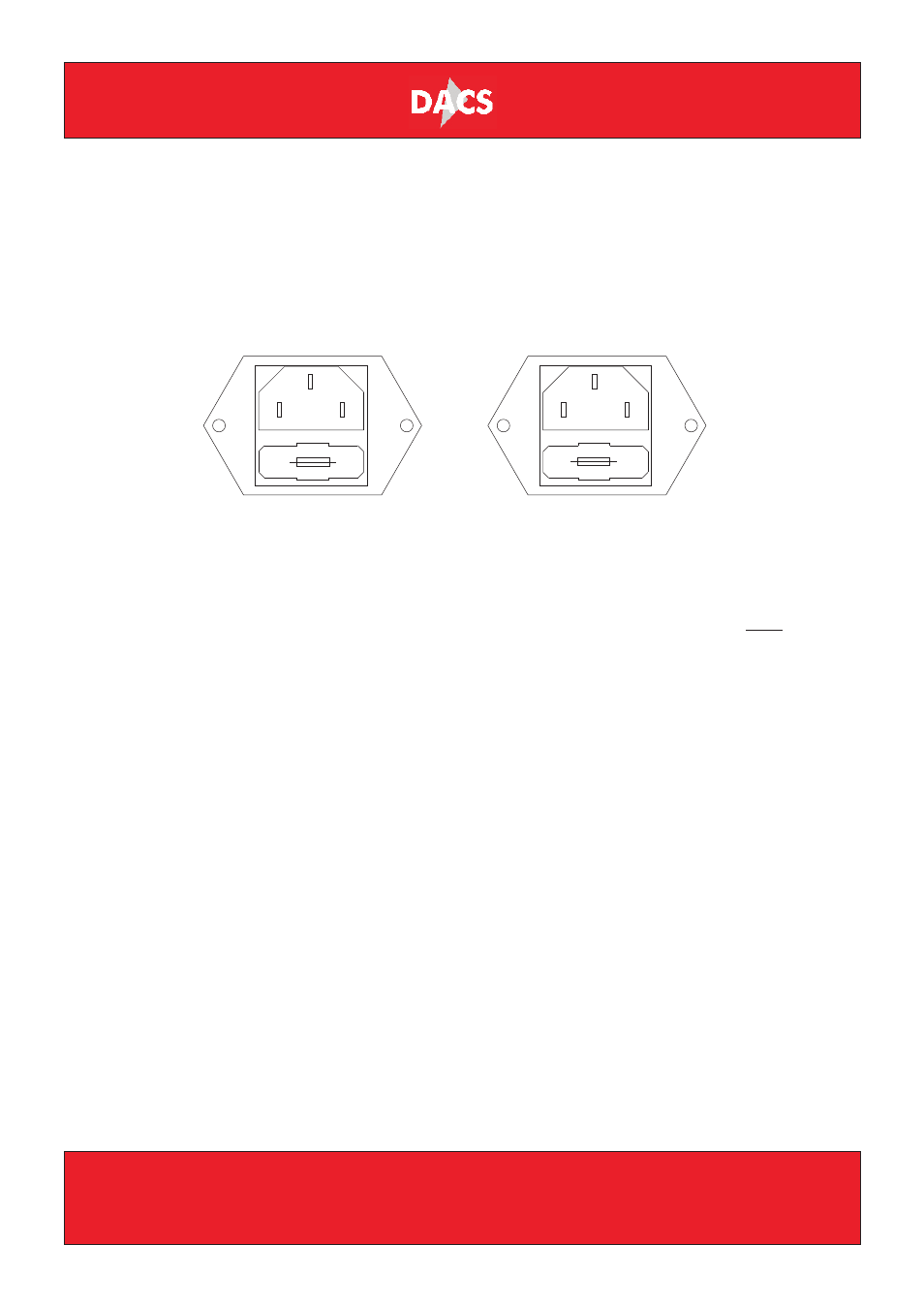
The unit will accept 240 VAC and 110 VAC mains supplies. The IEC inlet’s fuse holder
is used as a selector as shown in Fig 2. The factory setting is for 240 VAC.
Figure 2
2 Control Voltage Inputs
These inputs vary the frequency of the oscillator output over the range selected.
These inputs can be used with, and will combine with, any internal modulation. It
would thus be possible to use the OSC1 to frequency modulate OSC2 and to have
separate CV inputs modulating each oscillator. They are Volts/Hz control voltages.
3 Outputs from Internal Oscillators
These are the outputs from the oscillators as routed to the MOD inputs by the OSC
switch, after any CV processing. This means that if the internal FM switch is
activated, and additional control voltages routed to the CV inputs, OSC2 will be the
much modulated oscillator output. They are present even when the front panel OSC
switch is not activated.
4 MODule8or Input
As a rule of thumb, both MUSIC and MOD inputs should be between +2dBu and
+12dBu. This will give an output approximately equal to the two input signals, eg.
+4dBu MOD and MUSIC input ~ +4dBu output.
The MOD input is used to modulate the signal going to the MUSIC input. In most
cases the two inputs are interchangeable, but FwS series MODule8ors are
configured to favour this method of operation (in particular see 5 below). Modulation
tones or secondary signals should be fed into this input; if using subsonic LFOs to
modulate, this input will accept them.
240V
11
0V
Set for 240VAC
24
0V
110V
Set for 110VAC
DACS LTD, Stonehills, Shields Road, PELAW, Gateshead, Tyne and Wear NE10 0HW
Tel: +44 (0) 191 4382500 | Fax: +44 (0) 191 4382511 | www.dacs-audio.com | [email protected]