User controls – AJA D4E User Manual
Page 4
4
User Controls
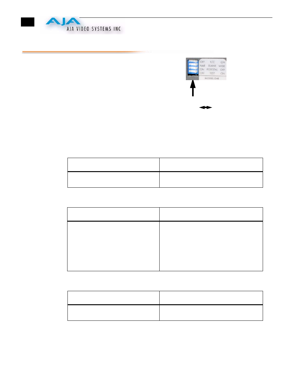
The user interface for the D10CE is a 4-switch
DIP accessible through a cut-out in the
bottom of the unit. Use the DIP switches to
configure output, pedestal, blanking, and
enable or disable the test signal output.
Switches 1 through 3 control the format of the
output BNC. Switch 4 turns the test signal on
and off. The exact function of each DIP switch
and what it controls is described on the
following pages.
Dip Switch Functions All dip switches are accessible through a cut-out in the bottom of
the unit.
Switch 1—Selects Y/C or Composite Output at the 2 Output
BNCs
:
Switch 2—Configure Blanking
:
Switch 3—Configure Pedestal For Composite/Sync BNC
:
Note:
There is no effect with 625 input.
Switch 4—Turn Test Signal Output On or Off
DIP Switches
OFF ON
ON
OFF
Selects Y/C (S-video) output at the two
BNCs)
Selects composite video output at the two BNCs
ON
OFF
WIDE Blanking:
Vertical—
Line numbers indicate where video starts)
line 20, field 1; line 20, field 2 (525 line)
line 23, field 1; line 336, field 2 (625 line)
Horizontal—
Active video line duration
ITU-R/SMPTE (710 pixels NTSC,
702 pixels PAL)
NARROW (NAR) Blanking:
Vertical—
Line numbers indicate where video starts
line 13, field 1; line 12, field 2 (525 line)
line 10, field 1; line 322, field 2 (625 line)
Horizontal—
Active video line duration's)
ITU-R.470 (720 pixels PAUNTSC)~-
ON
OFF
7.5 IRE pedestal for NTSC (also selects
BETA 525 levels for YPbPr)
No pedestal (also selects SMPTE levels for
YPbPr)