Pply the, Ifter to a, Positioning the lifter on the load – Wood’s Powr-Grip MT1HV11DC User Manual
Page 12: Sealing the lifter against the load
Rev 10.5/4-14
10
MT1/2HV11DC: #35081
CAUTION: Examine each air filter regularly, and empty when necessary.
The lifter is equipped with one or more air filters to help protect the vacuum system from
contaminants. In order for a filter to function, the operator must empty the filter bowl before
enough liquid accumulates to contact any portion of the filter element (see MAINTENANCE: A
IR
F
ILTER
M
AINTENANCE
).
T
O
A
PPLY THE
L
IFTER TO A
L
OAD
Positioning the Lifter on the Load
Make certain that the contact surfaces of the load and each vacuum pad are free of any
contaminates that could prevent a pad from sealing against the load (see MAINTENANCE: V
ACUUM
P
AD
M
AINTENANCE
). Center the lifter’s pad frame to within 2" [5 cm] of the load center, since off-
center loading can cause the load to tilt unexpectedly (see T
O
T
ILT THE
L
OAD
to follow), and it may
also damage the lifter.
4
Make sure that each vacuum pad will fit entirely on the load’s contact
surface (see SPECIFICATIONS: Pad Spread) and that it will be loaded evenly while lifting (see
SPECIFICATIONS: Per-Pad Load Capacity). Then apply the lifter to the load so that each pad is
touching the contact surface.
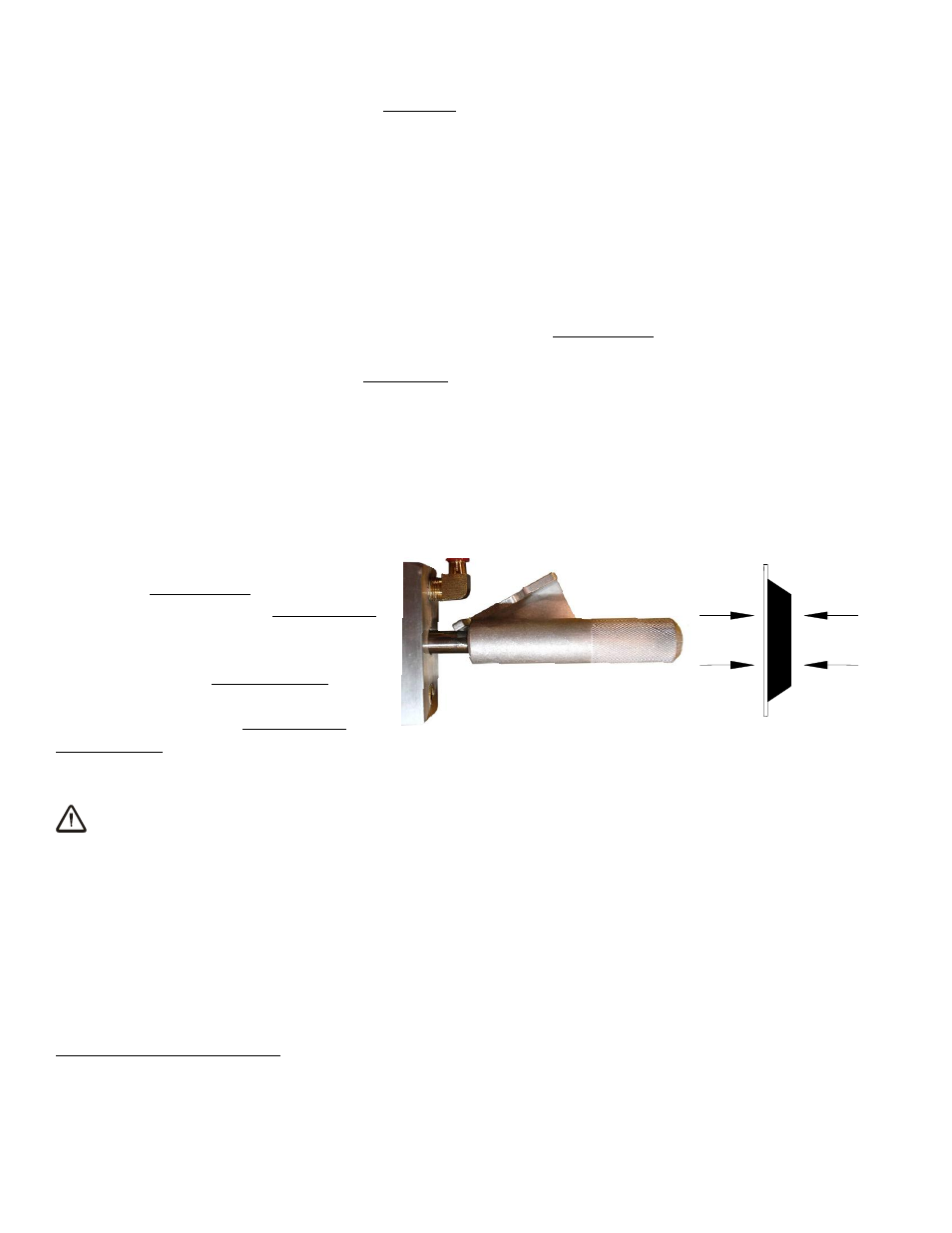
Sealing the Lifter against the Load
Firm pressure at the center of the lifter
helps each vacuum pad begin to seal
against the load. Pull the valve handle
outward until it latches securely in the
“APPLY” position (power on), as shown.
This energizes the vacuum pump,
causing air to be drawn at each pad
immediately. The red low vacuum
warning light also turns on and remains illuminated until the lifter attains sufficient vacuum to lift
the maximum load weight (see T
O
L
IFT AND
M
OVE THE
L
OAD
: Load Capacity and the Warning Light
to follow). The valve handle must remain in the “APPLY” position throughout the entire lift.
WARNING: Keep valve handle latched securely in “APPLY” position throughout
lift.
Note: If a vacuum pad has been lying against a hard object (as during shipping), it may be
slightly distorted. Although initially it may be difficult to apply the pad to a load, this condition
should correct itself with continued use.
4
The lifter is designed to handle the maximum load weight (see SPECIFICATIONS: Maximum Load Capacity) when the load’s
center of gravity is positioned within 2" [5 cm] of the pad frame’s center point. Occasional loading deviations are permissible,
provided that the operator can maintain control of the load at all times and that the load weight is low enough to avoid damaging
the lifter.
TO APPLY