Installation – Wood’s Powr-Grip LB7FAO User Manual
Page 4
Rev 0.1/10-10
2
LB7FAO: #35203AFT
INSTALLATION
I
NSTALLING THE
F
ORKLIFT
A
DAPTER ON A
L
IFTER
In order to be used successfully, the Forklift Adapter must be installed correctly on a Wood's
Powr-Grip model MRT4-DC vacuum lifter. If the Forklift Adapter is already installed as directed
below, proceed to the next section.
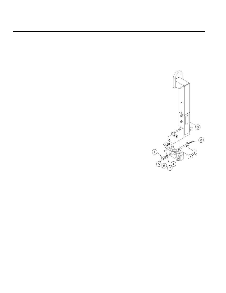
1) Remove the lift bar/center section assembly (shown in
illustration) from the lifter as follows: Make sure the pad frame
is supported independently. Identify the rotation pin (not
shown), which connects the center section (4) to the pad
frame. Remove the locking collar from the end of the rotation
pin and slide the center section off the pin.
2) Remove the lift bar (8) from the center section (4) as follows:
Identify the tilt pin (2), which connects the lift bar to the center
section. Remove the cotter pin (1) from one end of the tilt pin,
and remove the hex head bolt (3) and its washer from the
other end. This will enable you to slide the tilt pin out from the
center section.
Note: Prior to removing the tilt pin from the center section,
carefully take note of the placement and order of all associated
hardware, so that you will know how to reinstall the tilt pin.
Remove the tilt pin and the lift bar. Be sure to lay out the
outer flat washer (5), the foam washer (6) and the machine
bushings (7) in the appropriate order for reassembly.
3) Secure the Forklift Adapter in place of the lift bar (8) on the lifter as follows: First reverse the
procedure in step 2 to install the center section (4) on the Forklift Adapter. Be sure to install
the tilt pin (2) and all the associated hardware in the same order as originally installed. In
particular, the machine bushings (7) must go
inside
the plates of the Forklift Adapter. Make
sure that the hex head bolt (3) and a new cotter pin hold the tilt pin (2) securely in place.
Note: Clean hardware and replace any worn-out hardware, as necessary. In particular,
the
cotter pin must be replaced
, as it is only intended for one-time use (see REPLACEMENT
PARTS LIST).
Next, reverse the procedure in step 1 to reconnect the center section to the pad frame. Make
sure the locking collar is tightened securely on the rotation pin.
I
NSTALLING THE
A
DAPTED
L
IFTER ON A
F
ORKLIFT
Follow the directions for vacuum lifter ASSEMBLY in the MRT4-DC lifter's instruction manual, but
instead of suspending the lifter from a crane or other hoisting device, modify the procedure as
follows: