Ti.282-04 pg2, Rohs, Model pr-282 – MAMAC Systems PR-282 User Manual
Page 2: Technical information, Ma output, Differential pressure sensor, Page 2 of 4, Typical applications (wiring diagrams)
Model PR-282
Technical Information
TI.282-04
DIFFERENTIAL PRESSURE SENSOR
Page 2 of 4
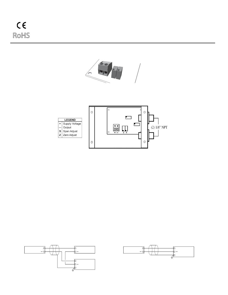
PR-282 Differential Pressure Transducer with mA Output
TYPICAL APPLICATIONS (wiring diagrams)
Wiring PR-282 Units with mA Output
Input Signal
+
Common
+
+
Shield/Ground
Controller / Meter / Recorder
mA Output Transducer Only
12-40 VDC Power Supply
Input Signal
+
Common
+
Shield/Ground
Controller / Meter / Recorder
mA Output Transducer Only
Figure 1 and Figure 2 illustrate typical wiring diagrams for the PR-282, 4-20 mA, 2-wire, Differential Pressure Transducer.
Figure 1 - Wiring for mA Differential Pressure Transducers with External DC Power
Supply
Figure 2 - Wiring for mA Differential Pressure Transducers where the Controller or
Meter has an Internal DC Power Supply
mA Output
RoHS
The PR-282 pressure transducers with 4-20 mA output units are powered with a 12-40 VDC supply.
The following describes the proper wiring of these pressure transducers with mA output:
1. Remove the terminal block by carefully pulling it off the circuit board.
2. Locate the [+] and [-] terminal markings on the board.
3. Attach the supply voltage to the [+] lead.
4. Connect the 4-20 mA output ([-] terminal) to the controller’s input terminal.
5. Ensure that the power supply common is attached to the common bus of the controller.
6. Re-insert the terminal block to the circuit board and apply power to the unit.
7. Check for the appropriate output signal using a DVM set on DC milliamps connected in series with the [-] terminal.
+
—
Z S