Flint & Walling City Pressure Booster VP10 User Manual
Page 3
3
95 North Oak Street • Kendallville, IN 46755 • © 2014 Flint & Walling, Inc. All rights reserved.
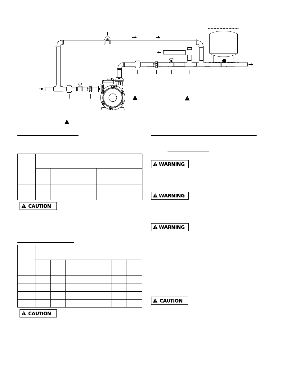
FIG 1 TYPICAL INSTALLATIONS
IL1213
Ball
Valve
#2
(Open)
City Water Main
only
Union
Home or Irrigation
1" Dia. Suction
Optional
Water
Tank
1" Dia. Discharge
Ball
Valve
#1
(Open)
Union
Ball Valve #3
(Closed)
IN
OUT
By-Pass
Drain
Pressure
Relief
Valve
(PRV)
Adjustable
Pressure
Regulator
(APR)
Adjustable
Pressure
Regulator
(APR)
#2
#1
#3
1/2 HP PERFORMANCE
See charts below for expected system pressure at
various incoming line pressure / flow rates.
Inlet
PSI
VP05 System Pressure (PSI)
at Flow Rates (GPM)
3
6
9
12
15
18
21
10
44
39
32
25
17
20
54
49
42
35
27
30*
64
59
52
45
37
Do not exceed 30 input PSI for
P/N VP05
*Note: Increase tank PSI (see FIG 3) if inlet PSI
will exceed preset tank setting 26 psi.
1 HP PERFORMANCE
Inlet
PSI
VP10 System Pressure (PSI)
at Flow Rates (GPM)
3
6
9
12
15
18
21
10
66
61
54
46
37
29
18
20
76
71
64
56
47
39
28
30
86
81
74
66
57
49
38
40**
96
91
84
76
67
59
48
50** 106 101
94
86
77
69
58
Do not exceed 50 input PSI for
P/N VP10
**Note: Increase Tank PSI (see FIG 3) if inlet PSI
will exceed preset tank setting 36 psi.
GENERAL PUMP INSTALLATION / SETUP (FIG 1)
City booster pump installation is shown per
FIG 1. During pump use, insure ball valves #1 and
#2 are open, and ball valve #3 is closed.
#1 An Adjustable Pressure
Regulator (APR#1) is required on the suction side of
the pump (see fig 1) if the incoming water pressure
can exceed the maximum input pressure.
#2 An Adjustable Pressure
Regulator (APR#2) is required on the Discharge
(See fig 1) to insure maximum water pressure does
not exceed local plumbing codes.
#3 A Pressure Relief Valve (PRV)
connected to a drain is required (see fig 1) to safe
guard plumbing from exceeding max pressures if the
Pressure Regulators fail. Typically the PRV would
be set 5 psi higher than the APR#2.
NOTE: Optional external water tank can be used to
decrease the on/off cycle rate of the pump system,
which can extend the life of the pump. (Typical tank
3 gallon draw down.) Set tank PSI equal to pump
tank PSI.
The entire system must be air and
water tight to maintain prime. Use thread tape on
all connections to insure no leaks. Hand tighten
all threads and then add additional half turn with
wrench.