Wiring the fan motor, Heater craft switches, Single-speed fan motor – Heater Craft 900H Series Hydronic Heaters User Manual
Page 6: Speed fan motor
Page 5
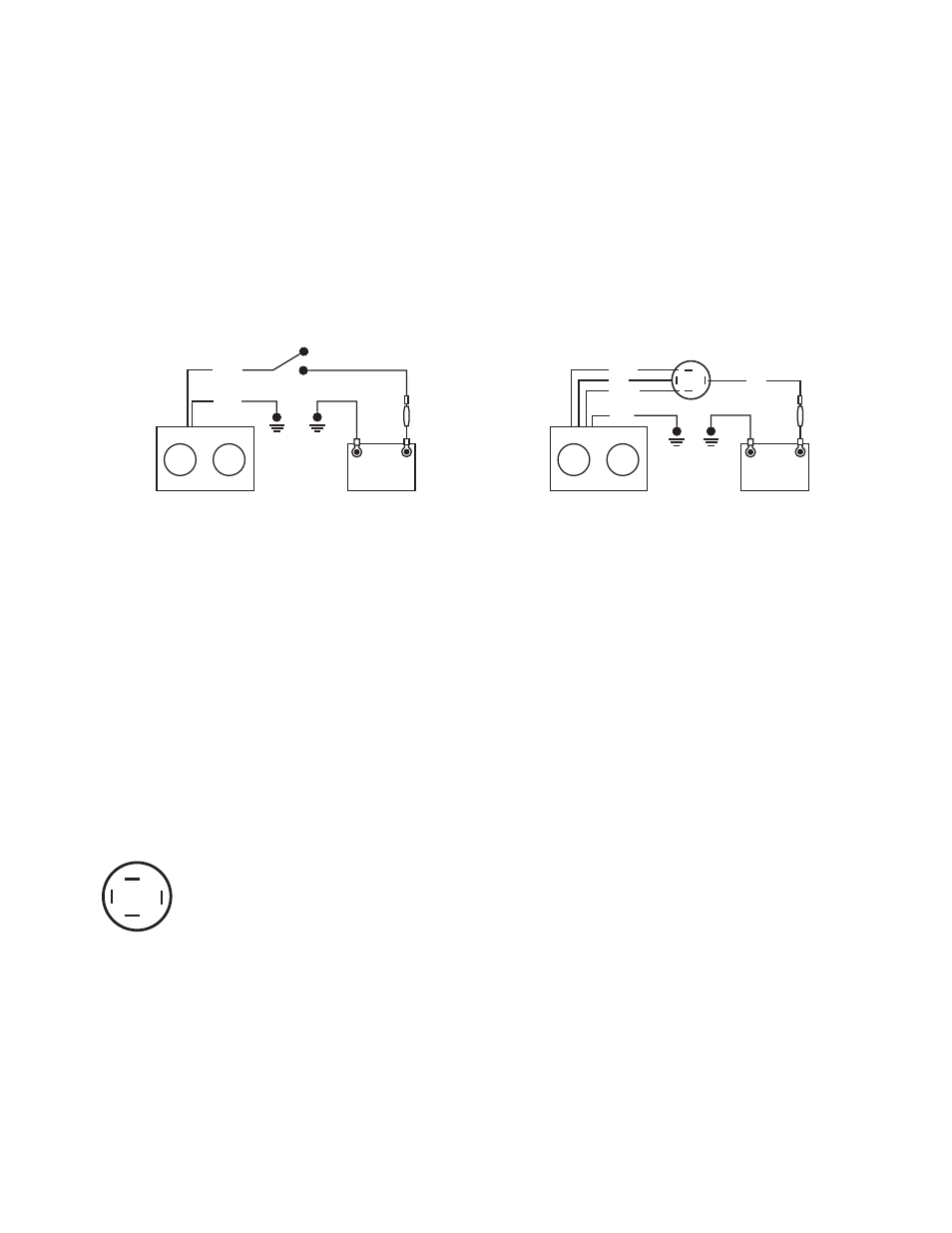
Wiring The Fan Motor
Single-speed fan motor:
The fan motor and switch should be protected
with an in-line fuse. The fuse rating should be
greater than the amperage draw of the fan
motor.
• Red or Yellow lead – on/off switch
(power source)
• Black lead – ground
3-speed fan motor:
A four-position switch is needed for full
operation. The fan motor and switch should be
protected with a 15-amp in-line fuse.
• Yellow lead – Low speed
• Red lead – Medium speed
• Orange lead – High speed
• Black lead – ground
Battery
+
–
Heater
Yellow
Black
Switch
Fuse
Battery
+
–
Heater
Yellow
Red
Red
Orange
Black
Fuse
Single-speed
fan motor
3-speed fan
motor
1
2
3
+
1. The wires from the heater unit are color-coded and correspond as follows.
2. Route the Black wire to a ground source and attach.
3. Route the fan wire to the fan switch and attach.
Heater Craft Switches
E-112 Switch and E-113 Mounting plate.
1. Locate a place to install the heater fan switch.
2. Drill the proper size hole for your installation:
• Without the switch mounting plate, drill a 7/16" hole.
• With the switch mounting plate, drill a 1 1/8" hole.
• To mount the switch plate, pre-drill a 5/64" hole for the mounting screws provided and
mount the switch plate.
E-112 Switch Wiring Diagram
Terminal 1 – Yellow wire, low-speed.
Terminal 2 – Red wire, medium speed.
H707 Switch and Mounting plate.
1. Locate a place to install the heater switch and switch plate.
2. Drill a 1 3/8" hole for the switch plate.
3. Pre-drill 7/64" holes to mount the switch plate.
4. Route the wires to the switch and mount the switch/switch plate assembly.
Note – Low speed wire has in-line resistor. High speed wire has no resistor. Center terminal – to power
source
1
2
3
+
Terminal 3 – Orange wire, high speed.
Terminal + – Red wire, fused power source.