Sectional views and parts identification, Basic design – Gradall 534B (9020-7317) Service Manual User Manual
Page 146
When either directional clutch is selected the opposite clutch is relieved of pressure and vents back through
the direction selector spool. The same procedure is used in the speed selector.
The direction or speed clutch assembly consists of a drum with internal splines and a bore to recieve a hy-
draulically actuated piston . The piston is “oil tight” by the use of sealing rings. A steel disc with external
splines is inserted into the drum and rests against the piston. Next , a friction disc with splines at the inner
diameter is inserted. Discs are alternated until the required total is achieved . A heavy back-up plate is then
inserted and secured with a snap ring. A Hub with O.D. splines is inserted into the splines of discs with
teeth on the inner diameter The discs and hub are free to increase is speed or rotate in the opposite direc-
tion as long as no pressure is present in that specific clutch.
To engage the clutch, as previously stated , the control valve is placed in the desired position. This allows
oil under pressure to flow from the control valve , through a passageway, to a chosen clutcth shaft. This shaft
has a drilled passageway for oil under pressure to enter the shaft. Oil pressure sealing rings are located on
the clutch shaft. These rings direct oil under pressure to a desired clutch. Pressure of the oil forces the piston
and discs against the heavy back-up plate. The discs, with teeth on the outer diameter clamping against
discs with teeth on the inner diameter , enables the hub and clutch shaft to be locked together and allows
them to drive as a unit.
There are balls or bleed orifices, depending upon the model, in the clutch piston which allow quick
e s c a p e f o r o i l w h e n t h e p r e s s u r e t o t h e p i s t o n i s r e l e a s e d .
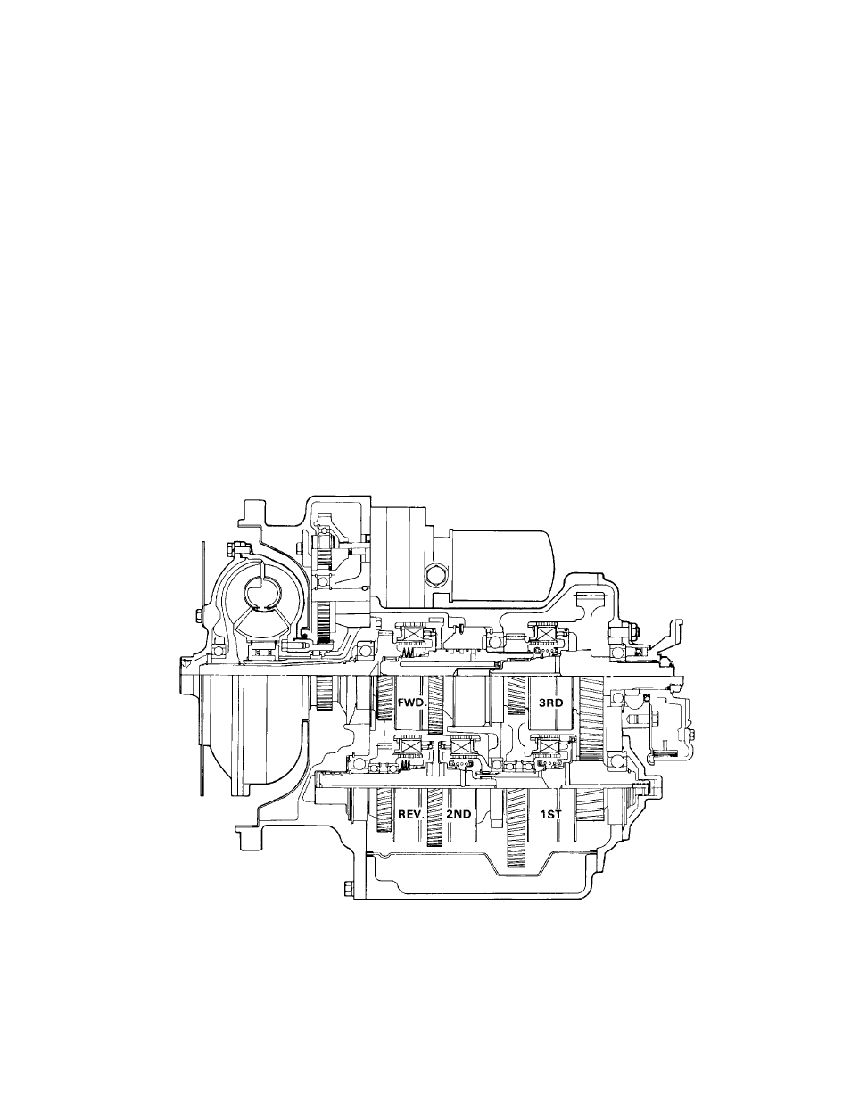
BASIC DESIGN
Figure A