Myron L 767 User Manual
Page 13
SECTION 4
Component Identification/Calibration and Preventive Maintenance
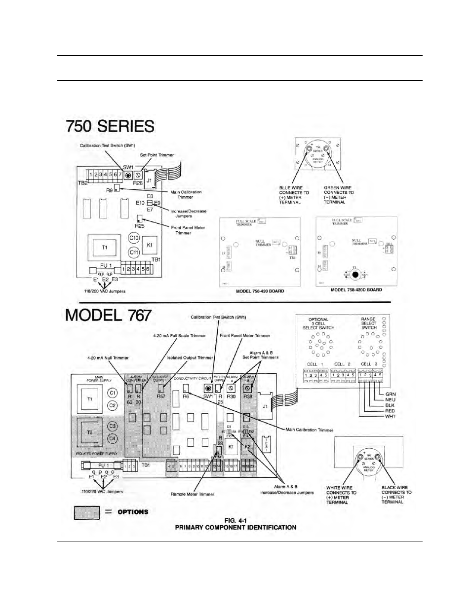
4.1 PRIMARY COMPONENT IDENTIFICATION
As identified in Section 3, the Conductivity Monitors’ switch and
indicator components are mounted directly to the front panel.
The Conductivity Monitors’ Control boards are contained within
and mounted to the back of the enclosure. The 767 Monitor,
when equipped with the 3 Cell Input option, has a second
component board mounted on the back of the front panel.
Model 758-420 and 758-420D have an additional board
mounted behind the front panel.
11