Rear panel controls and functions, Artist elite – Audio-Technica AEW-T1000A User Manual
Page 10
Artist Elite
®
4000 & 5000 Series Professional UHF Wireless Systems
10
Receiver Controls and Functions (Continued)
8 / 12 MODE/SET BUTTON: Use in conjunction with the Up/Down
arrow buttons to step through menus, choose operating
frequency and select receiver function options. The Mode/
Set button has different functions depending on the status of the
receiver. Two distinct operations are associated with this button:
Touch: A momentary press of the Mode/Set button. It is used to
enter Menu mode, to enter Edit mode, or to Escape
without making any changes to current settings.
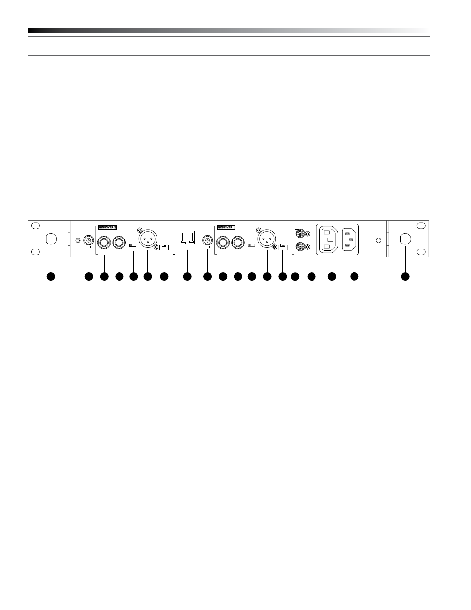
Fig. D
AEW-R5200 Receiver Rear Panel
Rear Panel Controls and Functions
(Fig. D)
14 ANTENNA INPUT JACK: BNC-type antenna connector for Tuner
“B.” Attach the antenna directly, or extend it with a low-loss
antenna cable. See the ”Antennas” section on page 7 for more
details. Antenna power at +12 volts is available at both antenna
jacks; select it via the LCD menu on Channel 1.
15 / 22 EXTERNAL MUTE: Permits manual and absolute muting of
the receiver via a
1
/
4
" TS phone jack and a user-provided external
switch. “Shorting” the jack (closing the switch connection) mutes
the receiver channel. When External Mute has been applied, the
only way to un-mute the receiver is to open the External Mute
switch connection.
16 / 23 INSTRUMENT OUTPUT JACK:
1
/
4
" transformer-isolated TRS
balanced phone jack output. Tip: “audio +”; Ring: “audio –”;
Sleeve: ground (shield). Can be connected to an aux-level input
of a mixer, guitar amp or tape recorder. Using the associated
Ground Lift switch permits feeding equipment with different
ground levels.
17 / 24 AF OUTPUT ATTENUATOR: Three-position switch adjusts
audio output level of both audio output jacks, with attenuation of
0 dB, –6 dB or –12 dB.
18 / 25 MIC OUTPUT JACK: XLRM-type connector. Pin 1: ground
(shield); Pin 2: “audio +”; Pin 3: “audio –”. A standard 2-conductor
shielded cable can be used to connect the receiver output to a
balanced microphone-level input on a mixer or integrated
amplifier. This output is transformer-isolated from the
1
/
4
" TRS
Instrument output jack.
19 / 26 GROUND LIFT SWITCH: Disconnects the ground of both the
Mic and Instrument output jacks on the associated receiver
channel. Normally, the switch should be to the right (ground
connected). If hum caused by a ground loop occurs, slide switch
to the left (ground lifted).
POWER
ON
OFF
MODE/SET
MODE/SET
IN
ANT. B
OUTPUT
(BAL)
INSTRUMENT
EXTERNAL
MUTE
0/-6/-12
ATTN (dB)
BALANCED
MIC OUTPUT
GROUND
LIFT
GROUND
NETWORK
INTERFACE
IN
ANT. A
OUTPUT
(BAL)
INSTRUMENT
EXTERNAL
MUTE
0/-6/-12
ATTN (dB)
BALANCED
MIC OUTPUT
GROUND
LIFT
GROUND
AC
˜
100V-240V
50/60Hz
OUTPUT
5A/500W MAX
WARNING:
THIS APPARATUS
MUST BE EARTHED.
IN
LINK
OUT
OUTPUT
PHONES
UHF SYNTHESIZED DIVERSITY RECEIVER AEW-R5200
MIN MAX
PUSH SEL
LEVEL
RX NAME
RX NAME
29
30
31
14 15 16 17 18
19
20
21 22 23 24 25 26 27
28
31
Hold: A press and hold (about two seconds) of the Mode/Set
button. It is used to accept a new setting when the
receiver is in Edit mode or to save the current settings to
one of the five user-defined name presets or the internal
memory location (“NAME?”).
13 FRONT-MOUNT ANTENNAS: Cables and panel connectors are
included with the AEW-R5200 to permit attaching antennas at the
front panel.
20 NETWORK INTERFACE CONNECTOR: An Ethernet connection
on the AEW-R5200 provides full communication and monitor/
control by an associated computer. See the separate AEW Control
Interface manual for computer setup and operation.
21 ANTENNA INPUT JACK: Connector for Tuner “A.” Attach the
antenna directly, or extend it with a low-loss antenna cable.
Antenna power at +12 volts is available at both antenna jacks.
27 LINK IN JACK: Connect the provided cable to this jack with the
index mark on the plug aligned toward the screw head to the right
of the jack. The receiver with a Link In and no Link Out connection
is the “Master” unit. (With an AEW-R5200 in the Master position,
its Channel 1 is the system’s Master and its Channel 2 is the first
“slave.”)
28 LINK OUT JACK: Connect the provided cable to this jack with the
index mark on the plug aligned toward the screw head to the right
of the jack. The receiver with a Link Out and no Link In connection
is the last slave in a multi-unit system.
29 AUXILIARY AC OUTLET: An auxiliary AC pass-through outlet and
included “jumper” power cordset simplify making power
connections to an array of AEW-R5200’s. Maximum output from
the auxiliary AC outlet is 5 Amperes.
30 AC POWER INPUT: IEC-type connector for 100V–240V AC,
50/60 Hz power input. No adjustment for mains voltage/
frequency is necessary.
31 REAR RACK MOUNT: Mounts are provided at the rear of the side
panels to permit attachment to rear rack rails in racks so equipped.
The additional support is especially helpful when equipment is
transported.