Pulsafeeder PULSAtron Series ET User Manual
Page 11
10
5.5 Operation By External Input Signals (Options):
The pump can be controlled by three types of input signals. All are fully isolated from AC input and from earth ground.
The input socket connections are located at the bottom of the control panel face and the signal cords are provided with
the pump. Remove rubber plugs to access plug sockets.
5.5.1 Stop Function (E+, A+, C+, C and HV only)
Operation of the pump can be stopped by an external signal input. When the external signal is input to the terminal
marked which is provided at the bottom of the control panel, the lamp (red) lights up and operation of the pump is
stopped. The stop function overrides both manual settings and external input.
Operation of more than one pump from the same contact closure will damage the pump circuits.
When such operation is required, the pump circuits must be electrically isolated from one another by means of a
multi-contact control relay or similar means.
The input signal must be in the form of closure of a mechanical relay or other mechanical switching device, or solid-state
relay or other solid-state switching device. Voltage signals are prohibited. The switching resistance of either mechanical
or solid-state devices must be 100 ohms or below when ON and 1 megohm or above when OFF. If any type of solid-state
device is employed, it must be installed with the proper polarity, if required for the device; and leakage current must not
exceed 200 microamperes to prevent false triggering in the OFF state.
The stop function is commonly used in conjunction with a tank float switch. The float switch contacts are normally open
but when the tank level falls past a certain point the contacts close and the pump stops.
5.5.2 External Pacing Function (E+, A+, C+, C and HV only)
The pump's stroke rate can be controlled by an external signal input. When the input signal line is connected and the
EXTERNAL /OFF /MANUAL switch is in the external position and a contact signal is input to the terminal marked
, the
pump makes one discharge stroke.
Operation of more than one pump from the same contact closure will damage the pump circuits.
When such operation is required, the pump circuits must be electrically isolated from one another by means of a
multi-contact control relay or similar means.
When the “ON” signal pulse is input, the pump operates one stroke and the fluid is discharged. In addition, the pump can
be operated continuously to its maximum strokes/min. by repeated
input of “ON” and “OFF” signals.
After receiving an input signal, the pump generates the necessary power pulse to actuate the solenoid. The external
signal input is debounced by the pump circuit. The pump will not stroke in response to a spurious or erratic input signal
that follows at a rate greater than its maximum strokes/minute. If the external signal rate exceeds its maximum
stokes/minute, the pump will stroke at half the external signal rate to prevent overdosing and to protect the pump from
overheating.
The input signal must be in the form of closure of a mechanical relay, other mechanical switching device, or of a solid-
state switching device. Voltage signals are prohibited. The switching resistance of either mechanical or solid-state
devices must be 100 ohms or below when ON and 1 megohm or above when OFF. If any type of solid-state device is
employed, it must be installed with proper polarity, if required for the device; and leakage current must not exceed 200
microamperes to prevent false triggering in the OFF state.
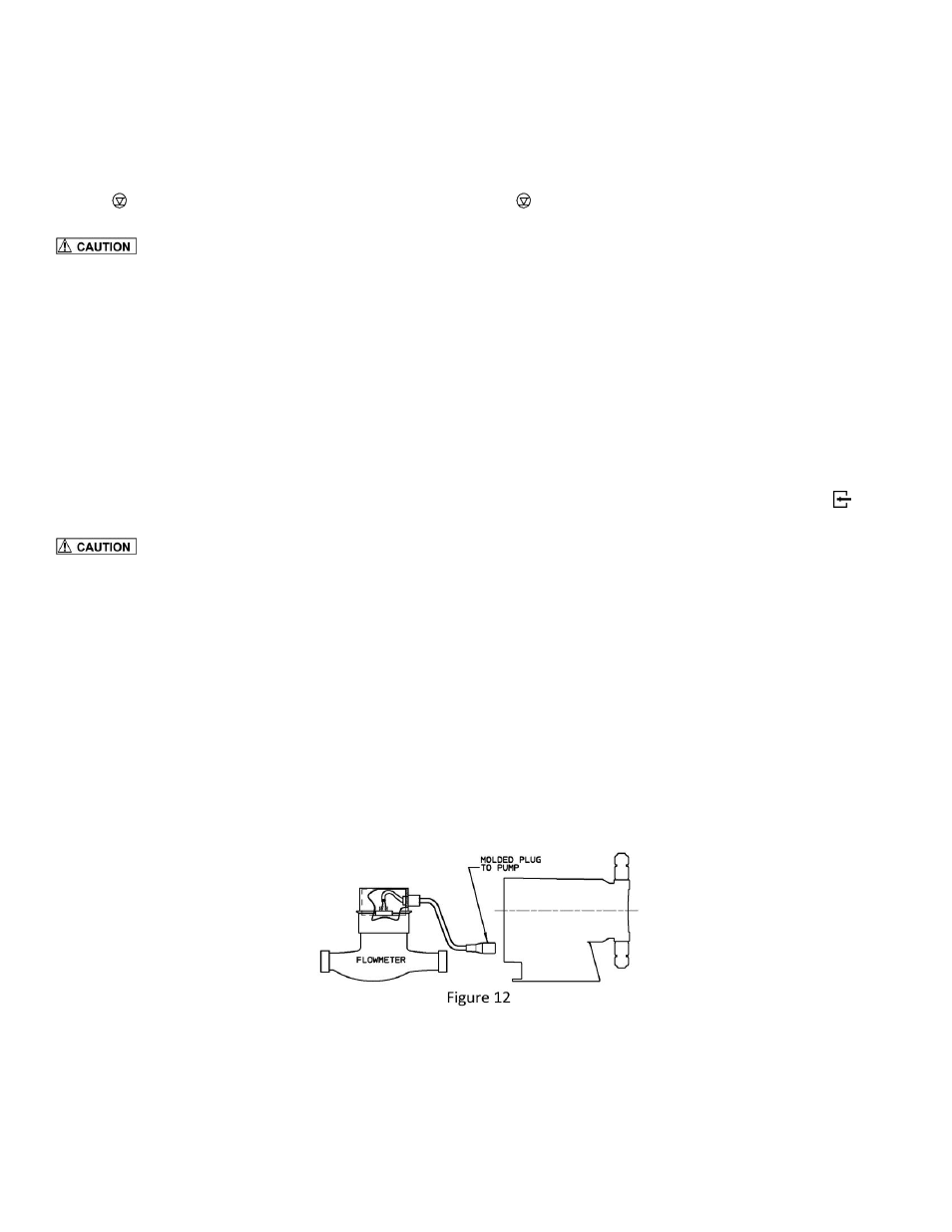
Cycle rate of the input signal should not exceed the maximum stroke/minute speed of the pump.
Typical wiring is shown at right for use with switch closure flow-meters. (Figure 12)
10 millisecond contact time required for each “ON” input signal.
5.5.3 4-20mA DC Input Function (E+ and HV only)
The pump’s stroke rate can also be controlled by a 4-20 mA DC signal to the terminal marked [4-20 mA].