Signal and power supply wiring, Figure 20, Screw terminal block on motherboard – Vaisala PTU300 User Manual
Page 42: Signal and power supply, Wiring
User's Guide _______________________________________________________________________
40 ___________________________________________________________________ M210796EN-G
Signal and Power Supply Wiring
When wiring the power supply module, see section Power Supply
Module on page 48.
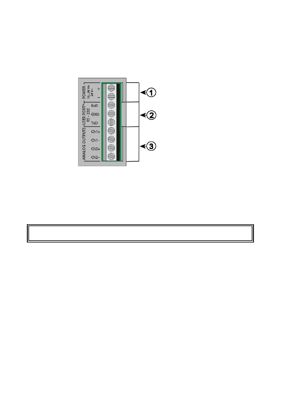
0506-028
Figure 20
Screw Terminal Block on Motherboard
The following numbers refer to Figure 20 above:
1
=
Power supply terminals 10 ... 35 VDC, 24 VAC
2
=
User port (RS-232 terminals)
3
=
Analog signal terminals
WARNING
Make sure that you connect only de-energized wires.
1.
Open the transmitter cover by taking out the four cover screws.
2.
Insert the power supply wires and signal wires through the cable
bushing in the bottom of the transmitter; see the grounding
instructions in the previous sections.
3.
Connect the analog output cables to terminals: Ch1 +, Ch1-, Ch2+,
Ch2-. Connect the RS-232 user port cables to terminals RxD, GND
and TxD. For more information about the RS-232 connection refer
to section Serial Line Communication on page 81.
4.
When wiring the optional modules, see the corresponding section
for instructions:
- RS-422/485 Interface on page 57
- Relays on page 55
- Third Analog Output on page 53
- WLAN Interface on page 62