Installation requirements, Before you install, Consider description – Amana RS2320006 User Manual
Page 21
A5
RS2320006 Rev. 0
Before You Install
Installation Requirements
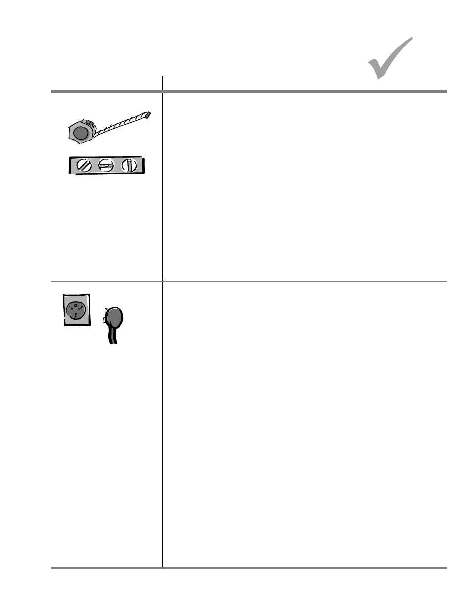
Consider
Description
Location
This range can be installed flush against right and left base cabinets, and rear
vertical wall. Range can also be installed flush against left or right vertical wall
extending above 36" standard countertop height.
Use dim ensions shown in this m anual to determ ine space needed for
installation.
Range m ust not be installed or stored in an area where it will be exposed to
water and/or weather. Range is heavy and m ust not be installed on soft flooring
such as cushioned vinyl or carpeting. If this type of flooring is present where the
range will sit, ¼ " thick sheet of plywood or sim ilar m aterial should be placed
where the range will be installed.
Irregular Cabinet and Countertop Heights
Countertops such as ceram ic tile tops cause cabinet and countertop to be higher
than 36". Follow instructions below when countertop is higher than 36".
1.
Raise leveling legs to m axim um height.
2.
Measure from floor to rangetop. If the height of the range is less than height
of countertop, floor m ust be shim m ed.
3.
Shim floor using a piece of plywood sam e size as range opening. Secure
plywood to floor. Plywood m ust be as secure as original flooring.
4.
Install anti-tip bracket and slide range into place.
Electrical Requirem ents
Electrical Supply
Range needs a 3 or 4 wire 240 Volt AC, 40 am p, 60 Hertz, 1 Phase electrical
supply. W iring system and grounding m ust conform with the latest edition of the
National Electric Code, ANSI/NFPA 70, or the Canadian Electrical Code, CSA
C22.1. Installation m ust conform to all local, m unicipal and state building codes,
and local utility regulations. Connect range to power supply with M AXIMUM
RATED VOLTAGE listed on the rating plate. Line voltage m ust not exceed rated
voltage.
Copper W ire
Term inal block is approved for copper wire connection only. If alum inum house
wiring is to be connected to the cooktop, use only connectors designed for
joining copper to alum inum and follow the m anufacturer’s recom m ended
procedure closely. The following procedure is suggested:
1. Connect length of copper building wire to range term inal block with ring
term inals.
2. Splice copper wires to alum inum wiring using connectors that are design
certified by Underwriter’s Laboratories and recognized for joining copper to
alum inum . Follow the connector m anufacturer’s recom m ended procedure.
3. W ire used, location and enclosure of splices m ust conform to local codes.
Pow er Cord
Power cord is not supplied with range. Power cord m ust be U.L. or C.S.A. listed
and m eet NEC and M obile Hom e Manufacturers Association Standards. Cord
m ust be rated at a m inim um 250V— 40 AMP, equipped with a plug configuration
in accordance with NEMA. Conductors m ust end with closed loop (ring)
term inals at the range.
• Three-conductor cord plug NEMA 10-50P allowed for residential in U.S.
• Four-conductor cord plug NEM A 14-50P required in Canada and for m ost
m obile hom e installations, but can be used for residential.
NOTE:
Only a power cord suitable for use with ranges m ay be used.
For installation in a m obile hom e, or area where local codes (Canada)
do not perm it grounding through the neutral term inal, a 4-wire cord
m ust be used.