4 wiring – Pyromation Series 442 User Manual
Page 2
Copyright 2006 Pyromation, Inc., All rights reserved.
2 of 11
Phone (260) 484-2580
•
FAX (260) 482-6805 or (800) 837-6805
•
www.pyromation.com
442-D
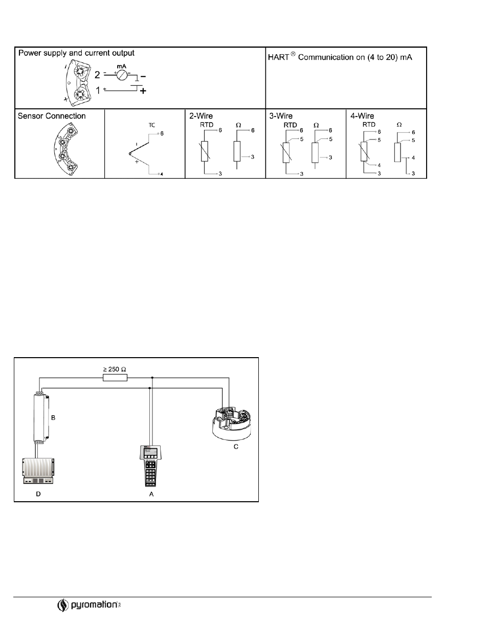
4 WIRING
4.1 Overview
Figure 4-1
Head transmitter wiring
4.2 Measurement unit connection
Attention: Switch off power supply before opening the housing cover. Do not install or connect the unit to power. If this is not
followed parts of the electronic circuit will be damaged.
• Sensors:
Connect the sensor leads to the respective head transmitter terminals (Terminals 3 to 6) by following the wiring diagram (see
figure 4-1).
• Output signal and power supply:
Connect dc power cables to terminals 1 and 2 according to the wiring diagram (see figure 4-1).
Hint: The screws on the terminals must be screwed tightly. Head transmitter configuration during measurement operation is
possible. There is no need to disconnect cables!
4.3 HART
connection
Connection is made directly using the (4 to 20) mA signal cables. Note: The measurement circuit must have a load of at least
250
Ω. See Figure 4-2 and 4-3.
Connection of a HART
hand operating module DXR 275
Figure 4-2
Electrical connection of the HART
operating module
A = HART
module
B = Loop power supply
C = HART
transmitter
D = PLC with passive input
Pos
. A
(11.5 to 30) V dc
(4 to 20) mA