WEN 5662 13 A 18 inch Electric Snow Thrower User Manual
Page 9
Upper F
Frame Assem
mbly
For easie
tape from
each han
Snow Th
er assembly,
m the factory
dles part, as
hrower.
the handle f
y. This tape
viewed from
frames are m
indicates the
m the operat
marked with y
e LEFT side
tor’s position
yellow
e of
n of the
Hold the
that the s
(Fig. 3)
upper frame
screw holes a
e with the ye
align with th
ellow tape on
he holes on th
n the LEFT
he middle fr
side so
rame.
Insert a T
handle. T
and tight
T-bolt into ea
Then attach
ten. (Fig. 4)
ach hole wit
a saddle wa
th the head o
sher and kno
on the inside
ob on the ou
of the
utside
Repeat thhis step on thhe other sidee of the handdle.
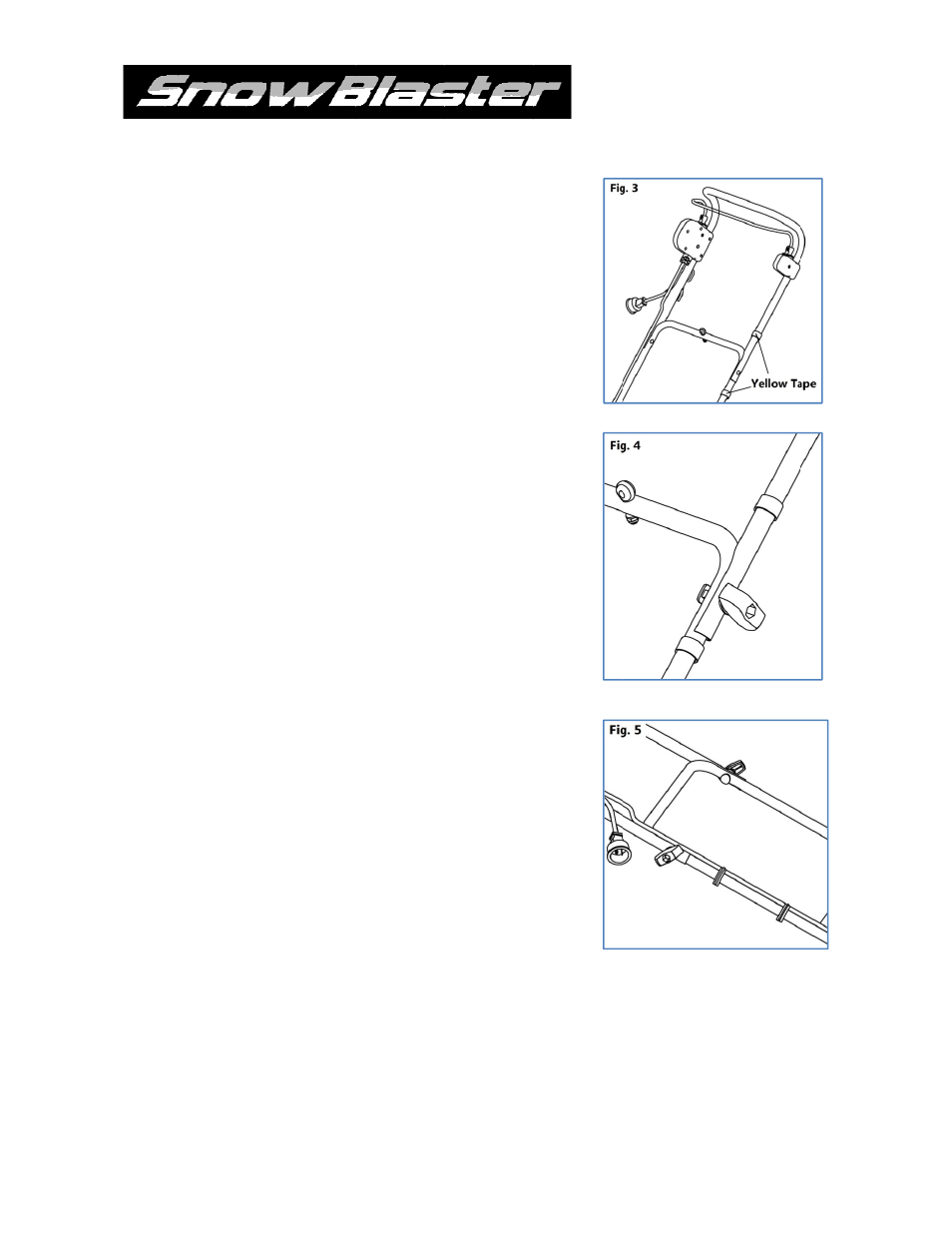
Locate th
cord to th
evenly sp
he three Cab
he frame of t
paced interva
le Clips in th
the unit by c
als. (Fig. 5)
he parts bag
clipping them
. Secure the
m onto the fr
power
rame at
#5662 SNOW THROWEER OPERATOR
R’S MANUAL
9