Farm Star 720 User Manual
Page 21
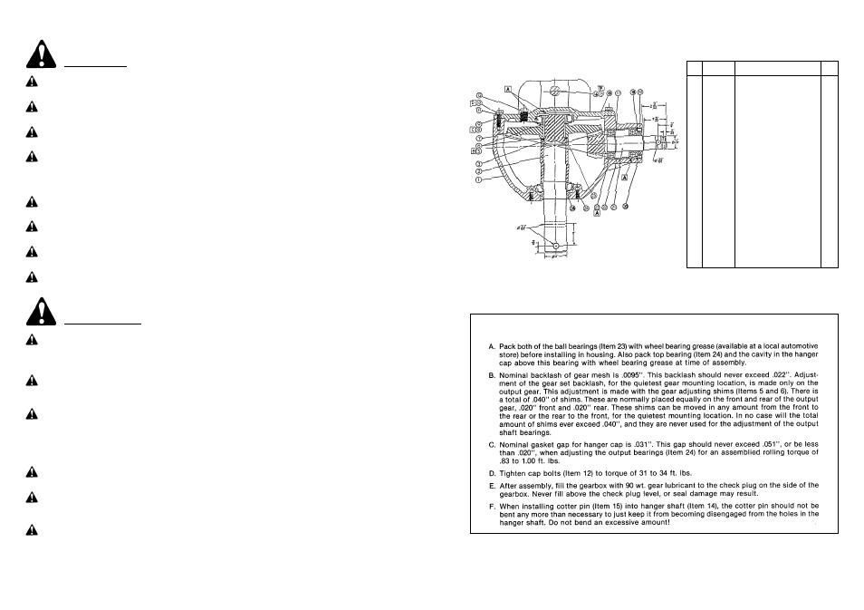
G E A R B O X R E PA I R P R O C E D U R E
3
20
S A F E T Y I N S T R U C T I O N S
(continued)
Keep safety signs clean and legible at all times.
Replace safety signs that are missing or have become illegible.
Replaced parts that displayed a safety sign should also display the current sign.
Safety signs are available from your Distributor or Dealer Parts Department or the factory.
Be sure that the installation area is clean and dry. Be sure temperature is above 50˚F (10˚C).
Decide on the exact position before you remove the backing paper.
Remove the smallest portion of the split backing paper. Align the sign over the specified area and carefully
press the small portion with the exposed sticky backing in place.
Slowly peel back the remaining paper and carefully smooth the remaining portion of the sign in place. Small
air pockets can be pierced with a pin and smoothed out using the piece of sign backing paper.
How to Install Safety Signs:
SAFETY SIGNS
Safety is a primary concern in the design and manufacture of our products. Unfortunately, our efforts to provide
safe equipment can be wiped out by a single careless act of an operator. It is the operator’s responsibility to
read and understand ALL Safety and Operating instructions in the manual and to follow these. Accidents can
be avoided.
Know your controls and how to stop tractor, engine, and implement quickly in an emergency. Read this manual
and the one provided with your tractor.
In addition to the design and configuration of equipment, hazard control and accident prevention are depen-
dent upon the awareness, concern, prudence and proper training of personnel involved in the operation, trans-
port, maintenance and storage of equipment.
Train all new personnel and review instructions frequently with existing workers. A person who has not read
and understood all operating and safety instructions is not qualified to operate the machine. An untrained
operator exposes himself and bystanders to possible serious injury or death.
Working with unfamiliar equipment can lead to careless injuries. Read this manual, and the manual for your
tractor, before assembly or operating, to acquaint yourself with the machines. It is the implement owner’s
responsibility, if this machine is used by any person other than yourself, is loaned or rented, to make certain
that the operator, prior to operating:
1. Reads and understands the operator’s manuals.
2. Is instructed in safe and proper use.
SAFETY TRAINING
Do not allow children to operate this machine.
1
706120
Housing
1
2
706121
Output Shaft
1
3
706122
Output Bearing Spacer
1
5
706123
Gear Adjusting Shim 0.30
Var.
6
706124
Gear Adjusting Shim 0.50
Var.
7
706125
Output Gear, 38 Tooth
1
8
706126
Output Cap Gasket 0.10
Var.
9
706127
Output Cap Gasket 0.25
Var.
11
706128
#10 Lockwasher
8
12
706129
M10 x 1.5 x 30 Cap Screw
8
13
706130
1
/
2
” Pipe Plug
2
14
706096
Hanger Shaft
1
15
706097
Cotter Pin
2
16
706131
Hanger Cap
1
17
706132
Retaining Ring
1
18
706133
Retaining Ring
1
19
706134
Seal Adapter
1
20
706135
Input Seal
1
21
706136
11 Tooth Pinion & Shaft
1
22
706137
Bearing Spacer
1
23
706138
207K Ball Bearing
2
24
706139
Bearing Assembly 7210
2
25
706140
Retaining Ring
1
26
706141
Output Seal 70 x 50 x 12
1
PART
NO.
DESCRIPTION
NO.
REQ.
REF.
NO.
G E A R B O X R E PAIR PA RT S