MP Pumps LI-L SQUIRT STAINLESS STEEL CENTRIFUGAL PUMP INSTRUCTION User Manual
Page 2
PIPING/MOUNTING:
The pump inlet and outlet has 3/4” pipe connections. Use
pipe sealant on the threads and other connections. The base
does not require direct mounting if one of the pipe flanges is
rigid mounted. Do not rigid mount both the flanges and the
base to avoid mounting tolerances that may distort the motor
base. Install the pump with the shaft in a horizontal direction.
Never install the pump vertical with the motor below the pump.
ELECTRICAL:
The motor must be protected from over current by using a
fuse or circuit breaker (see chart below for correct protection).
The proper minimum wire size is stated for each voltage
application. Make sure that the pump has the proper voltage
rating to match the installation power. Do not use or install if
the voltage on the label is different that the installation. All
wire connections must be secure and sealed to protect
arcing. Follow all local installation codes.
MOTOR VOLTAGE FUSE/CB WIRE SIZE
ON NAME PLATE AMPS AWG
12VDC 15 14
24VDC 10 16
32VDC 6 18
110VAC 2 18
OPERATION:
The pump should be operated with liquid in the pump
otherwise seal damage may occur. If an inlet valve is present,
the valve should always be completely open during
operation to avoid cavitation. An outlet valve may be used to
throttle the flow rate. Avoid repeated starts and stops; the pump
can operate for a long period of time without any flow. DC
motors are brush type and may emit a noise from the brush
that can sound like a squeal, this is normal. The pump will be
extremely quiet unless there is air in the system.
REPAIR AND MAINTENANCE:
DC motor brush life expectancy is 6,000 hours total brush life.
The motor is not rebuildable after the brushes have worn to
the limits.
The pump has a carbon/ceramic seal that may last several
thousand hours based upon the application. If the motor is
replaced, the mechanical shaft seal should also be replaced.
A seal that leaks will show leakage through the slot between
the pump housing and the motor. Extreme leakage may
damage the motor bearings and contaminate the inside of the
motor.
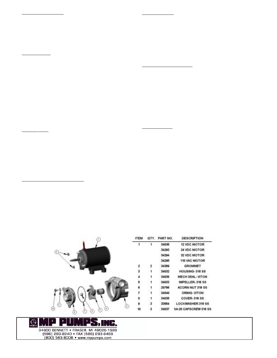
DISASSEMBLY:
1. Remove three cover screws and remove the cover,
discarding the o-ring.
2. Secure the impeller and remove the impeller locknut.
Pull the impeller straight out off the motor shaft.
3. Remove the seal-rotating porting by pulling the seal off
by hand.
4. Remove the two capscrews that hold the pump
housing onto the motor. Remove the pump housing
and push the seal seat out using a screwdriver.
INSPECT PUMP PARTS:
Always replace the mechanical seal. Check the seal for dry
run wear or damage. Check the motor shaft for wear at the
secondary sealing surface from the mechanical seal. If worn,
replace the motor. Check the motor bearings by rotating
the motor by hand. If the shaft rotation is not smooth or has
radial/axial endplay, replace the motor. Check the impeller
running surface between the impeller and cover. If the
surfaces are worn or irregular, replace each item.
Clean the parts that are to be reused using a solvent or
mild cleaner. Remove abrasive material.
REASSEMBLY:
1. Press the new seal seat into the pump housing. A light
lubricant may be used to aid the assembly. Install the
pump housing onto the motor and fasten the screws
through the motor.
2. Install the rotating portion of the mechanical seal by
sliding the seal over the motor shaft. Do not use any
lubricant.
3. Place the impeller onto the shaft over the “D” drive
against the shoulder and tighten the impeller lock nut
until the impeller is securely shouldered on the motor
shaft. Thread locking grade Loctite should be used to
secure the nut.
4. Stretch the o-ring over the cover pilot. Install the cover
onto the housing and fasten the capscrews and
lockwashers.
Check the pump for internal interference by rotating the
impeller. The pump should rotate freely with only seal
friction.
FORM 3805A (05-04)